
The dangerous shortcut to avoid
A solar panel and a battery both have two terminals, so connecting positive to positive and negative to negative can look obvious. That direct connection is usually the wrong approach. A panel's voltage and current change with sunlight, temperature, and load. A rechargeable battery needs controlled charging that matches its chemistry, voltage, and charging stage requirements. The device that manages that relationship is the solar charge controller.
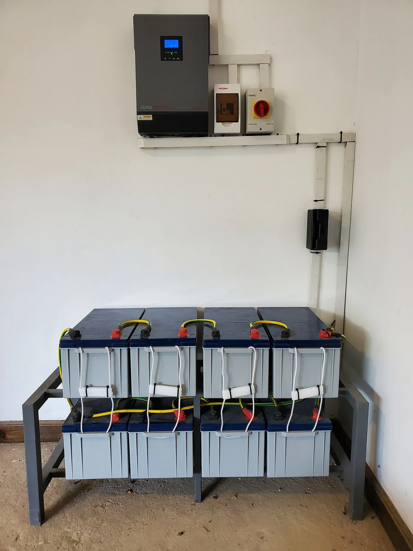
The normal power path is panel to charge controller, then charge controller to battery. Protection devices, disconnects, and correctly sized conductors belong in that path as required by the equipment instructions and applicable electrical rules. The physical sequence matters too. Many controllers need a battery connection before the photovoltaic input so they can detect system voltage and establish a stable reference.
This guide explains the physical solar panel to battery wiring process. It does not select the controller's current rating or determine how many panels can be placed in series. Those are design calculations covered in the controller sizing and array wiring articles. Here, the goal is a clean installation that respects polarity, protection, routing, connection order, and safe commissioning.
The complete power path
A basic off-grid charging circuit includes more than a panel and battery. Understanding every part before cutting cable prevents improvisation during the installation.
| Component | Job in the circuit | What must be verified |
|---|---|---|
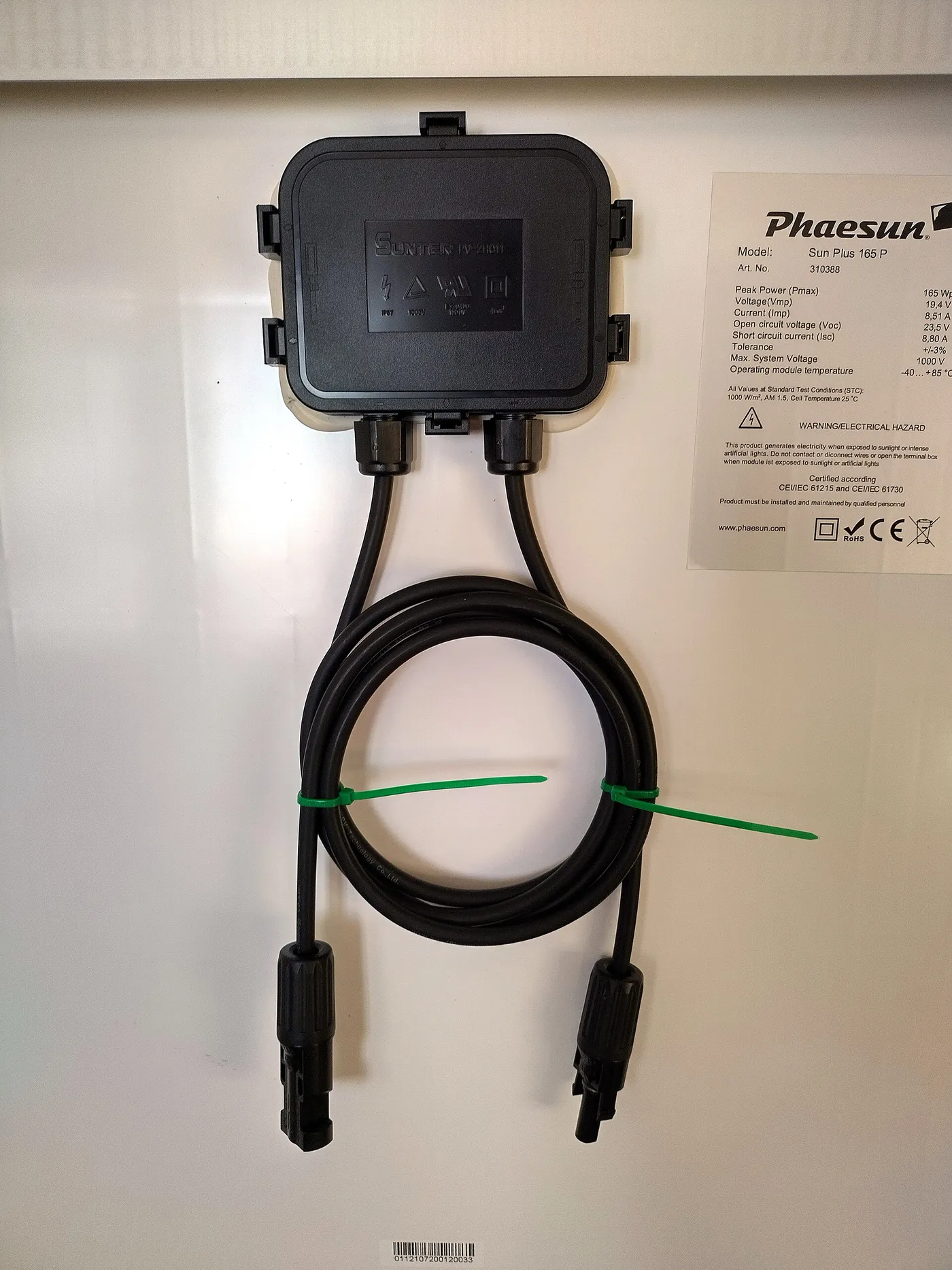
| Solar panel or array | Produces DC electricity when illuminated | Voc, Isc, Vmp, Imp, polarity, connectors, and temperature data |
| PV disconnect or breaker | Provides an approved way to isolate the solar input | DC voltage rating, current rating, interrupt rating, and polarity requirements |
| Charge controller | Regulates energy delivered to the battery | PV input limits, battery voltage, battery profile, and terminal capacity |
| Battery-side fuse or breaker | Protects the conductor against excessive current from the battery | DC rating, size, location, cable protection, and manufacturer instructions |
| Battery bank | Stores energy and supplies connected DC loads or an inverter | Chemistry, nominal voltage, BMS requirements, terminals, and charging limits |
| Conductors and connectors | Carry current between components | Ampacity, voltage drop, insulation, environment, termination, and strain relief |
The battery is not a passive endpoint. It can deliver very high fault current into a short circuit. That is why protection near the battery positive terminal is critical. The panel side can also remain energized whenever light reaches the cells. Both sources must be considered during service.
Why the charge controller belongs between them
A charge controller regulates voltage and current according to a configured battery profile. Depending on the equipment, it may provide bulk, absorption, float, or chemistry-specific charging behavior. It also prevents the panel from continuing to push energy into a battery after the permitted charging condition has been reached.
Direct panel-to-battery wiring can expose the battery to inappropriate voltage or prolonged charging. It also removes the controller's monitoring, low-temperature restrictions, and charging stages. A small maintenance panel may occasionally include regulation within its cable assembly, but that means a controller is still present. Never assume a product is regulated merely because it is marketed as a battery charger.
The controller must match the battery and array. A PWM and an MPPT controller handle the panel input differently, as explained in PWM vs MPPT charge controllers. The separate guide to sizing a solar charge controller covers PV open circuit voltage in cold weather, array current, controller output current, and battery voltage. Complete those checks before wiring begins.
Collect the right information first
Photograph or record every equipment label before installation. For each panel, capture rated power, open circuit voltage, short circuit current, maximum power voltage, maximum power current, and temperature coefficients. For the controller, record maximum PV voltage, maximum PV current where specified, rated battery charging current, compatible battery voltages, terminal wire range, and required protection.
For the battery, record chemistry, nominal voltage, maximum charging current, required charging profile, low-temperature charging restriction, BMS instructions, and terminal torque. A lithium battery may prohibit charging below a stated temperature unless it has approved internal heating or protection. An AGM battery requires a charging profile suitable for sealed lead-acid construction.
Create a one-line diagram showing the panel, disconnect, controller, battery protection, battery, and any busbars. Mark positive and negative throughout. A drawing exposes missing protection and unclear cable paths before hardware is mounted. Keep the final drawing with the equipment manuals for future troubleshooting.
Choose a safe controller location
Mount the controller on a stable surface in the orientation and clearances required by its manual. Keep ventilation openings unobstructed. Controllers generate heat, especially near rated output, and a sealed cabinet can cause thermal derating or shutdown.
Place the controller reasonably close to the battery to limit voltage drop on the high-current charging side, but do not mount it where battery gases, electrolyte, water, or excessive heat can reach it. Flooded lead-acid batteries require particular attention to ventilation and ignition sources. Follow the battery and controller separation instructions.
The location should permit inspection of terminals and indicators without dismantling furniture. Avoid areas used for loose cargo. In an RV, vibration and road movement require secure mounting, supported cables, grommets through panels, and strain relief near terminals. Do not allow cable weight to hang from a controller connector.
Plan conductors for ampacity and voltage drop
Wire size has two jobs. It must safely carry the expected current in its installation environment, and it must keep voltage drop within an acceptable range. A conductor can be large enough to avoid overheating yet still create enough voltage drop to interfere with charging performance.
Use the controller manufacturer's conductor guidance and applicable electrical rules. Account for conductor material, insulation temperature rating, bundling, ambient temperature, conduit fill, and whether the cable is exposed to oil, water, sunlight, or movement. Use flexible cable where the equipment and installation call for it, but never substitute an automotive cable without verifying its insulation and listing for the location.
Calculate the full circuit length, including the outgoing and return conductors. The battery side often carries higher current than the PV input side in an MPPT system because the controller converts higher panel voltage into lower battery voltage at increased current. Size each circuit from its own current and length rather than using one cable size everywhere.
Terminals also set a limit. A large cable that does not fit the controller terminal must not be trimmed until only a few strands enter. Use the permitted wire range or approved distribution hardware. Every strand should be captured, and no bare copper should remain exposed outside the terminal.
Use correct DC protection
Fuses and breakers protect conductors, not just appliances. The device must be rated for direct current at or above the circuit voltage and must have adequate interrupt capacity. An AC-only breaker may not safely extinguish a DC arc.
Battery-side protection normally belongs as close to the positive battery terminal as the installation rules and equipment permit. This minimizes the length of unprotected conductor capable of being energized by the battery. If a positive cable rubs through its insulation before the fuse, the fuse cannot clear that fault.
The PV side may require string fuses, array overcurrent protection, or a disconnect depending on panel configuration, available fault current, and equipment instructions. A single small string may not require the same protection as several parallel strings, but it still needs an approved isolation method where required. Do not copy a fuse size from an unrelated diagram.
A breaker used as a disconnect must be suitable for that purpose and installed with the correct polarity if it is polarized. Label disconnects clearly. In an emergency, a person should be able to identify PV input, controller output, and battery isolation without tracing hidden cables.
Verify polarity before every connection
Reverse polarity can damage a controller, trip protection, or create a dangerous arc. Never rely only on insulation color, especially in an older RV where previous work may not follow a standard. Use a suitable meter to verify polarity and voltage at each cable end before connecting it to equipment.
On the panel side, verify the connector polarity from the panel documentation and meter reading. Solar connector housings can confuse new installers because the physical male or female shell does not necessarily describe the electrical polarity. Adapter cables may also reverse the expected arrangement.
On the battery side, trace conductors to their actual terminals. Apply permanent positive and negative labels at both ends. If a cable passes through a wall or bundle, label it before routing so it cannot be confused with another black conductor later.
Make reliable terminations
A high-resistance connection generates heat and wastes energy. Use lugs, ferrules, connectors, and crimp tooling approved for the conductor and terminal. A lug sized for a different cable may appear tight while leaving voids that weaken the connection.
Follow the equipment torque specification with a suitable torque tool. Too little torque can allow movement and heating. Too much can damage a terminal block, crush strands, or strip hardware. Do not place soldered wire ends into screw terminals unless the manufacturer explicitly allows it because solder can creep under pressure.
Support cables so vibration and movement do not load the terminal. Use insulated covers on battery positive connections and barriers where tools could bridge between terminals. Route positive and negative conductors together where appropriate to reduce loop area, while respecting heat and separation requirements.
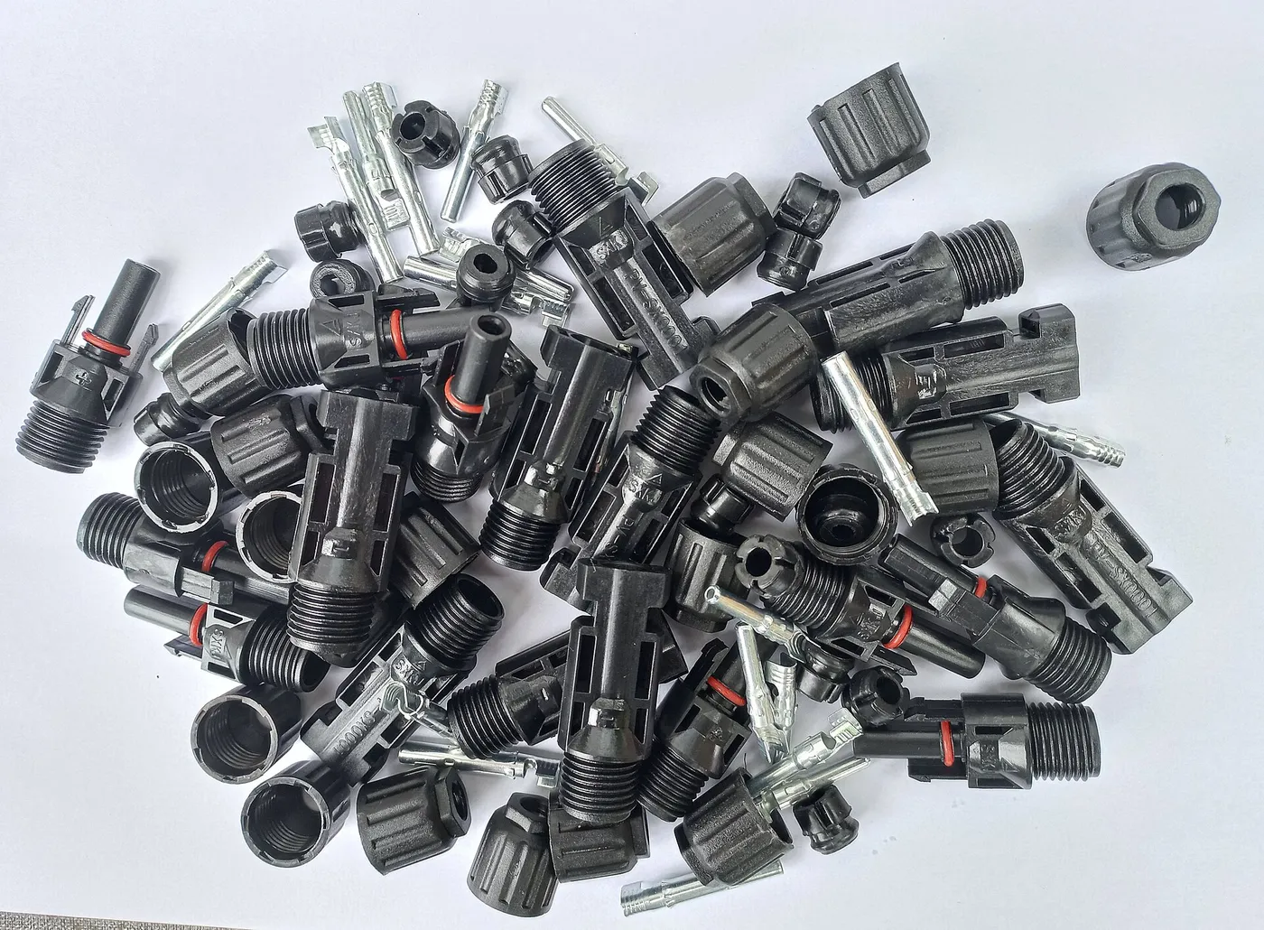
Solar connectors require compatible components and proper crimping. Mixing connector brands or visually similar parts can create a poor seal or unreliable contact. Do not use generic pliers to fold a contact around the conductor. Perform the prescribed pull check and confirm the seal is seated.
Connect the battery side first
Many standalone solar controllers require the battery to be connected before the PV input. The battery allows the controller to power up, identify nominal system voltage, and accept configuration. Always use the exact startup order in the manual because some integrated equipment may differ.
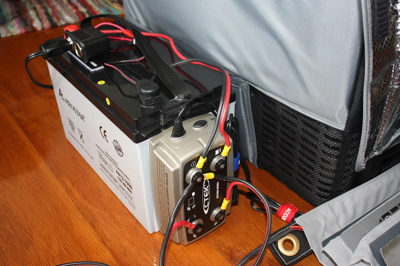
With all sources isolated, confirm the battery-side fuse is removed or breaker is open. Connect the controller battery conductors with correct polarity. Connect negative according to the system design, then complete the protected positive path as directed. Ensure tools cannot bridge the battery terminals.
Close the battery disconnect or install the specified fuse only after every termination has been checked. The controller should power up from the battery. Confirm that its display or application reports the expected battery voltage. Configure battery chemistry, charging voltages, current limits, temperature compensation, and any BMS communication required by the manuals.
If the controller does not power up or reports unexpected voltage, open the disconnect and investigate. Do not connect the solar input hoping that additional voltage will correct a battery-side problem.
Connect the panel side second
Keep the PV disconnect open while routing and terminating panel conductors. If practical and permitted by the manufacturer, keep the panel face covered and out of strong light during work. Remember that covering is not a substitute for an approved disconnect or safe electrical procedure.
Verify array polarity and measure open circuit voltage at the controller end before connection. Compare the reading with the expected array value and the controller limit. A reading with reversed sign indicates reversed meter lead relationship or reversed circuit polarity. Resolve the discrepancy before proceeding.
Connect the PV conductors to the correct controller terminals and torque them as specified. Confirm no loose strands are present. Close covers and strain reliefs. Then close the PV disconnect according to the startup order. The controller should recognize solar input and begin charging when battery conditions allow.
A controller may show little or no charging even in sunlight if the battery is full, the battery is too cold to accept charge, the PV voltage is below the startup threshold, or a protection condition is active. Diagnose the status instead of assuming the wiring is defective.
Series and parallel wiring change the input
When panels are connected in series, their voltage adds while string current remains governed by the current of the string. When panels are connected in parallel, current adds while voltage remains near the individual panel operating voltage. Those relationships change conductor current, protection needs, connector layout, and controller limits.
Cold conditions raise panel open circuit voltage, so a series string that fits the controller rating at standard test conditions may exceed it on a cold bright morning. Parallel strings increase available fault current and can trigger string protection requirements. The full design method belongs in series vs parallel solar wiring.
For a simple kit, use only the configuration approved by the kit manufacturer. The best RV solar panel kits guide can help identify packaged systems, but a kit is not permission to skip its diagram. Do not add another panel without recalculating controller voltage and current limits.
Grounding, bonding, and RV chassis questions
Grounding requirements depend on system voltage, controller topology, inverter design, vehicle construction, and applicable rules. Do not assume battery negative must always be bonded to the chassis, or that every controller permits a common negative. Some devices switch or monitor a conductor in ways that a casual bond can defeat.
Follow the controller, inverter, battery monitor, and RV manufacturer instructions as one coordinated design. Protective equipment grounding, DC negative bonding, and AC neutral bonding are different functions. A connection that is correct in one system may create parallel current paths or nuisance faults in another.
Metal panel frames and mounting structures may require bonding. Use approved hardware and corrosion control, and do not rely on an uncertain mechanical roof contact. Qualified help is appropriate when the manuals appear to conflict or when an inverter and shore power system share the installation.
Portable and foldable panel connections
A portable panel introduces connectors that are repeatedly handled, exposed to dirt, and routed across a campsite. Use a compatible controller and cable set, keep connectors dry and off the ground, and protect cables from doors, tires, chairs, and foot traffic.
Do not extend a cable without checking voltage drop and current rating. A long light-gauge extension can waste much of the energy that portability was intended to capture. Coiled cable can also trap heat under high current. Fully deploy it as instructed.
Some folding panels include a controller attached to the rear. Others provide raw panel output intended for a power station or separate controller. Confirm which arrangement is present before connecting it to a battery. Buyers comparing deployment formats can review the best foldable solar panels and smaller solar panel options, then verify that the selected product's output is compatible with the charging equipment.
Commission the system methodically
Commissioning is more than seeing a charging icon. Record battery voltage before startup, PV open circuit voltage before connection, controller status after battery connection, and charging current after PV connection. Compare readings with the expected weather and battery state.
Inspect every connection for heat after the system has operated under a meaningful load and charge level, using a safe method that does not expose live conductors. An unexpected hot terminal suggests resistance, an undersized conductor, a loose connection, corrosion, or damaged hardware. Shut down in the approved order before correction.
Confirm that the controller charging profile matches the battery manual. Test disconnect operation and label every device. Secure covers, cable clamps, and entry seals. Store the one-line drawing, settings, torque values, fuse types, conductor sizes, and commissioning readings with the manuals.
Safe shutdown and maintenance
Use the shutdown order specified by the controller manufacturer. Many systems isolate PV first and battery second, reversing the startup sequence, but the manual is authoritative. A controller that loses its battery reference while PV remains connected can behave unpredictably or be damaged.
Inspect cables, connectors, strain relief, seals, mounting, and battery terminals on a schedule appropriate for the vehicle and environment. Look for discoloration, melted insulation, cracked connector housings, corrosion, loose hardware, abrasion, rodent damage, and water intrusion. Correct the root cause rather than merely replacing a fuse.
Keep the panel clean only by methods approved by its manufacturer. Do not work on wet equipment or during unsafe roof conditions. A panel continues producing electricity under light, so maintenance planning must isolate both the battery and PV sources.
Frequently asked questions
Can I connect a solar panel directly to a battery?
Normally no. Use a compatible solar charge controller between them. A product sold as a battery maintainer may have regulation built into its cable or enclosure, but that must be confirmed in the documentation.
Which connection should be made first?
Many standalone controllers require the battery first and PV second. This lets the controller identify system voltage and initialize. Follow the exact controller manual because integrated systems can use a different procedure.
Where should the battery fuse be installed?
Battery-side protection is generally placed as close to the positive battery terminal as the applicable rules and equipment instructions permit. Its rating must protect the conductor and be suitable for the DC voltage and available fault current.
Can I use ordinary household wire?
Use conductors approved for the voltage, current, environment, movement, temperature, and termination method. A cable acceptable in a stationary wall may not be suitable for sunlight, water, vibration, or flexible RV routing.
Why does the controller show no charging in sunlight?
The battery may already be full, PV voltage may be below the startup requirement, a disconnect may be open, polarity may be wrong, or battery temperature protection may be active. Read the controller status and troubleshoot systematically.
Can different solar panels share one controller?
They can only be combined after checking their voltage and current characteristics, wiring configuration, cold-weather Voc, and controller limits. Mismatched panels may reduce production. Do not combine them solely because their watt ratings look similar.
Bottom line
Safe solar panel to battery wiring uses a compatible charge controller, correctly sized conductors, DC-rated protection, verified polarity, reliable terminations, and the startup order specified by the manufacturer. Plan the complete path before mounting equipment. Protect the battery conductor near its source, isolate the PV input with approved equipment, connect the battery side first when the manual requires it, configure the battery profile, and connect the panel side only after checking voltage and polarity. A careful installation is easier to inspect, safer to service, and far more likely to deliver dependable charging on the road or off the grid.