
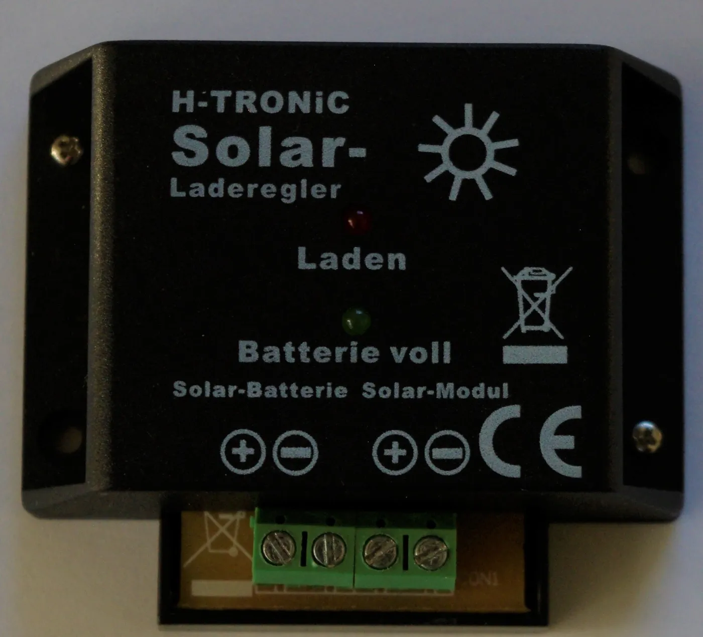
The choice is about conversion, not a better switch
The common PWM vs MPPT question is often reduced to a slogan: PWM is basic and MPPT is efficient. That shortcut points in the right direction but does not explain why the difference exists or when it matters. Both devices regulate energy moving from a photovoltaic array into a battery. They protect the battery from uncontrolled charging and move through charging stages according to their programming. Their key difference is how they handle the electrical mismatch between the panel's best operating point and the voltage the battery requires.
A pulse width modulation controller, usually shortened to PWM, behaves much like an electronically controlled connection between the array and battery. During active charging, panel voltage is pulled toward battery voltage. An MPPT controller, short for maximum power point tracking, lets the array operate at a higher voltage near its most productive point and uses a DC to DC converter to transform that input into the lower voltage and higher current needed by the battery.
That conversion ability can recover energy a PWM controller cannot use when panel operating voltage sits well above charging voltage. It also allows array configurations that reduce cable current. It does not make every MPPT installation automatically efficient or safe. A controller with the wrong input limits, incorrect battery settings, poor cooling, undersized conductors, or excessive standby consumption can still be a bad match.
Begin with actual array voltage, battery voltage, cable distance, climate, operating conditions, and charging requirements. Product category comes after those facts.
What a charge controller actually controls
A photovoltaic module produces electrical power whenever sufficient light reaches it. Its voltage and current change with sunlight, temperature, and the connected load. A battery, meanwhile, needs a controlled charging profile. Sending panel output directly into a battery can overcharge it, damage it, or create unsafe conditions.
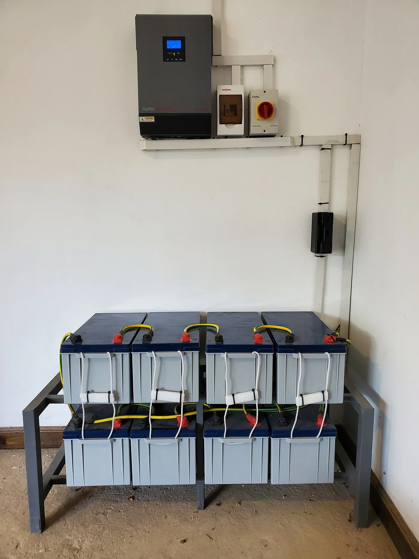
The charge controller sits between the array and battery. It limits energy flow and applies charging stages appropriate to the selected battery profile. Depending on the equipment, those stages may include bulk charging, an absorption period, float maintenance, and specialized behavior such as equalization for certain lead acid batteries. Lithium batteries use different voltage limits and may depend on a battery management system for cell level protection.
How a PWM controller works
A PWM controller changes charging current by rapidly switching the connection between the solar array and battery. The width of each on pulse changes as the controller regulates battery voltage. During the main charging stage, the array is effectively tied close to the battery's present charging voltage.
Consider a panel whose maximum power voltage is higher than the battery charging voltage. When a PWM controller pulls that panel down toward battery voltage, much of the voltage difference is not converted into extra charging current. The panel may deliver roughly its available current at the lower operating voltage, but it is no longer working at the voltage where the product of volts and amps is greatest.
This behavior is why PWM works best when the panel's electrical characteristics are closely matched to the battery bank. A nominal panel intended for a nominal 12 volt battery, for example, has enough voltage headroom to charge the battery under expected conditions without being so far above it that a large voltage difference is routinely left unused.
PWM controllers are electrically straightforward and can have low self consumption. For a small system with a short cable run, a modest array, and matched panel and battery voltages, the energy difference may not justify greater controller complexity. Simplicity can also make a well documented PWM system easy to understand and troubleshoot.
The limitation becomes obvious when higher voltage modules are used, when panels are wired in series, or when low battery voltage creates a larger gap between array maximum power voltage and charging voltage. PWM cannot transform that unused voltage into additional output current.
How an MPPT controller works
An MPPT controller separates the array's operating voltage from the battery's charging voltage. Its tracking algorithm adjusts the electrical load presented to the panels, searches for the point where panel voltage multiplied by current produces the most power, and then uses a DC to DC conversion stage to deliver that power at a suitable battery charging voltage.
If the array produces power at a voltage substantially above battery voltage, the converter lowers voltage and raises available output current, subject to efficiency and controller limits. Energy is conserved apart from conversion losses. The controller does not create power. It makes better use of the power available at the array's operating point.
The maximum power point moves as irradiance and cell temperature change. Strong sun, passing clouds, morning light, and panel heating alter the current voltage curve. The MPPT algorithm periodically adjusts to follow that movement. Tracking quality can differ among products, particularly in partial shade where the power curve may have multiple local peaks.
MPPT also enables the use of a higher array voltage with a lower voltage battery bank, as long as every input specification is respected. Higher array voltage can reduce current on the panel side for the same power, helping limit voltage drop over longer cable runs. The controller still needs appropriately sized conductors and overcurrent protection.
PWM vs MPPT comparison table
| Factor | PWM controller | MPPT controller |
|---|---|---|
| Array operating voltage | Pulled close to battery charging voltage | Held near the tracked maximum power voltage |
| Voltage conversion | Does not convert surplus panel voltage into output current | Uses DC to DC conversion to trade input voltage for charging current |
| Best array relationship | Panel voltage closely matched to battery voltage | Array voltage can be substantially above battery voltage within limits |
| Series strings | Often a poor fit because surplus voltage is not harvested | Common when cold corrected input voltage remains within rating |
| Long panel cable runs | Lower array voltage means higher current for a given power | Higher array voltage can reduce current and voltage drop |
| Energy harvest | Good in a small, closely matched system | Usually higher when array and battery voltages differ |
| Complexity | Simpler conversion method | More complex tracking and conversion electronics |
| Critical design limits | Input current, voltage match, output rating, and battery profile | Cold corrected Voc, input current, output current, power, and battery profile |
Where MPPT gains come from
The strongest MPPT advantage appears when the panel's maximum power voltage is well above the voltage at which the battery is charging. A PWM controller forces the panel toward the lower battery voltage. An MPPT controller keeps the panel near its more productive point and converts the voltage difference into charging current.
Cool panels tend to operate at higher voltage than hot panels, so the conversion opportunity can be larger in cool, bright conditions. A deeply discharged battery can also create a wider voltage gap during early charging. As battery voltage rises and panel voltage falls with heat, the relative advantage may narrow.
Higher voltage array wiring creates another benefit. For a given amount of power, increasing voltage lowers current. Lower current reduces resistive loss in a conductor, since cable loss rises with the square of current. An MPPT controller can accept the higher array voltage and convert it for the battery, provided cold weather open circuit voltage never exceeds the controller's maximum.
The panel side of that question is covered in solar panel output explained. It separates laboratory watt ratings from field output before controller losses are considered.
When PWM is a reasonable choice
PWM can be appropriate for a compact system using a panel designed to charge the battery's nominal voltage, with short conductors and limited expansion plans. Examples include a maintenance panel, a small lighting system, or a modest RV installation where energy demand is low and the panel remains close to the controller.
A suitable PWM design starts with voltage compatibility. The panel must provide enough operating voltage to charge the battery in hot conditions, yet not rely on a large unused voltage margin. Controller current rating, battery profile, conductor size, protection, and temperature compensation must still be correct.
Low self consumption can matter in very small systems. If a controller's own electronics consume a noticeable share of the energy collected by a tiny panel, theoretical conversion benefits may not translate into a better daily balance. Compare published standby and operating consumption rather than assuming either category always uses less.
PWM is less attractive when expansion is likely. Adding panels in series usually wastes the additional voltage at the battery connection, while adding panels in parallel increases current and cable requirements. A system that will grow may benefit from an MPPT architecture chosen with adequate voltage, current, and power headroom.
When MPPT is the stronger fit
MPPT is usually the stronger choice for medium and large arrays, higher voltage modules, series strings, long array cable runs, and systems expected to operate across wide temperature or irradiance ranges. It is also useful when roof space is limited and the owner wants to recover as much available panel power as practical.
An RV may have panels on the roof but the controller near the battery bank. Raising array voltage through a compatible series configuration can reduce current along the roof cable run. The MPPT controller then converts that energy for the battery. Series wiring also changes shade behavior and cold voltage, so it is not automatically preferable in every layout.
A power station or solar generator already contains a charge controller. External panels must match its published solar input voltage, current, and connector requirements. Buyers comparing integrated products can use the best solar generators and best RV solar generators guides, then verify the input specifications of the exact model.
MPPT can also support a deliberate higher voltage battery system. The related article on 12V vs 24V vs 48V systems explains how system voltage affects current and conductor demands. Controller selection must match the battery voltage and its charging profile.
Cold weather Voc is a hard limit
The most important MPPT input check is not a simple watts divided by volts formula. It is whether the array's maximum possible open circuit voltage remains below the controller's absolute input limit at the coldest expected cell temperature.
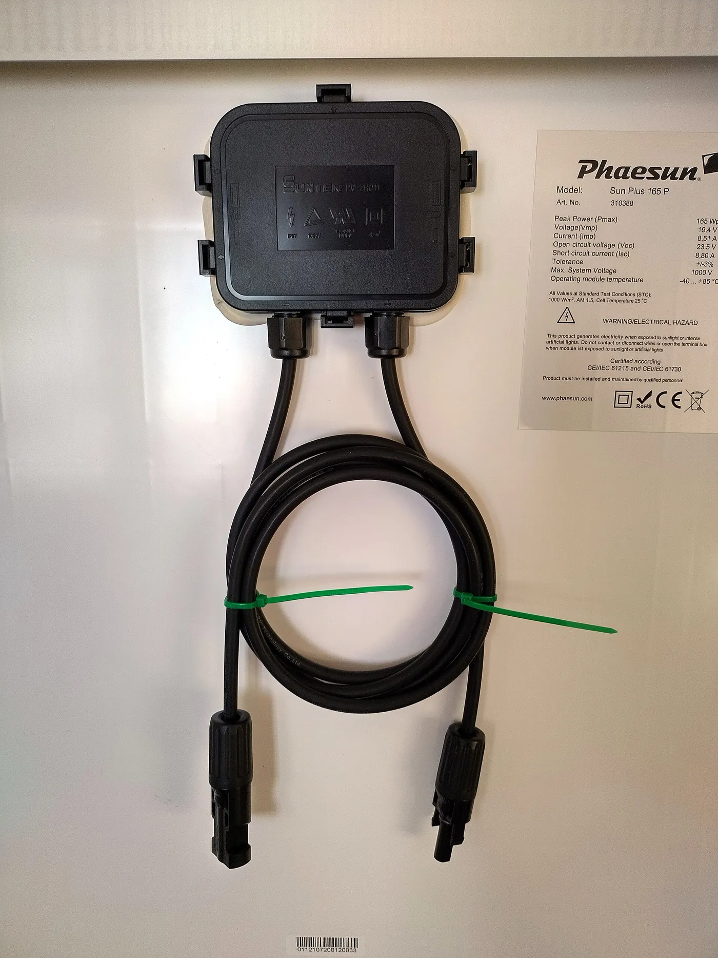
Panel voltage rises as temperature falls. Add the open circuit voltage of panels connected in series, then correct it using the module's voltage temperature coefficient and the expected minimum temperature. Parallel strings do not add voltage, but they do add current. The controller manufacturer's sizing method and applicable electrical rules govern the final calculation.
Exceeding the maximum PV voltage can damage a controller. A sunny cold morning is often the critical condition because the array can be cold while receiving enough light to produce open circuit voltage. Designing only from the standard test condition Voc printed in large type can therefore leave no safe margin.
PWM equipment also has maximum input voltage limits, but its normal use with voltage matched panels often produces shorter strings. The limit remains real and must be checked for the actual configuration.
The detailed arithmetic belongs in how to size a solar charge controller. This comparison establishes why cold corrected Voc is central to MPPT selection.
Output current and battery limits matter too
An MPPT controller may accept a high voltage, low current array and deliver a much higher current on the battery side. The controller's rated charging current must be adequate, and the battery must be allowed to accept that current. A battery management system may disconnect charging when a limit is exceeded, but routine design should not depend on emergency protection.
Lead acid batteries may require charging current within a recommended range and temperature compensated voltage. Lithium batteries may have a strict maximum charge current, low temperature charging restrictions, and required communication with compatible equipment. Select the battery profile specified by the battery manufacturer rather than choosing a generic label based only on chemistry.
Controller output conductors and protection must be sized for the maximum possible charging current, not the lower array side current. Keep the controller close to the battery when instructed so voltage sensing remains accurate and the high current cable run stays short.
Shade and multiple power peaks
Partial shade can create several peaks on an array's power curve. A basic tracking algorithm may settle on a local peak instead of the highest available one. Some controllers periodically scan a wider voltage range to find a better operating point. Manufacturers may describe this as global or full range tracking.
Do not select MPPT as a substitute for shade planning. Place panels away from repeatable shadows when possible, then configure the array to remain within voltage and current limits. The dedicated articles on series versus parallel wiring and solar panel angle and shading losses address those choices without expanding them here.
Battery profiles and temperature sensing
Controller type does not guarantee charging quality. Review the available battery profiles, adjustable voltage limits, absorption controls, float behavior, equalization settings, and low temperature response. A controller designed around lead acid assumptions may not be suitable for a lithium battery without a verified lithium profile.
Temperature sensing serves different purposes. For lead acid batteries, charging voltage is commonly adjusted with battery temperature. For lithium systems, the battery management system may prohibit charging below a defined cell temperature. A temperature sensor on the controller is useful only when the controller uses it in a way compatible with the battery.
Remote voltage sensing can improve regulation when charging current creates voltage drop between controller and battery. Communication between controller, battery monitor, and battery management system can provide better coordination, but only when the devices are documented as compatible.
RV and portable system considerations
Vehicle roofs offer limited area and frequent partial shade, while the battery compartment may be several cable meters from the panels. These conditions often favor MPPT because higher array voltage reduces current on the roof run and the controller can recover the voltage difference at the battery.

A preassembled RV solar panel kit can simplify component matching, but the included controller still needs to be checked against the exact panel configuration and battery. A kit label does not prove that every optional expansion remains within controller limits.
For a basic panel comparison before choosing the rest of the equipment, the best RV solar panels guide focuses the purchase on module dimensions, output, and intended installation.
Safety and installation rules
Solar modules produce voltage in light, even when the battery disconnect is open. Follow the required connection order in the controller manual. Many controllers must detect battery voltage before the PV input is connected so they can identify the system voltage correctly.
Use appropriately rated disconnects, fuses or breakers, conductors, connectors, and enclosures on both sides of the controller. DC arcs can persist, so do not unplug connectors under load unless the equipment is specifically rated and instructed for that operation.
Observe polarity. Reverse battery or PV polarity can damage equipment even when a product advertises protection. Verify with a suitable meter and the wiring diagrams before making the final connection. Cover or isolate panels according to the approved procedure while working.
Keep battery overcurrent protection close to the battery positive terminal as required by the system design. A battery can deliver fault current far beyond the controller's normal charging current. Controller electronics do not replace a correctly rated protective device.
Grounding and bonding depend on system architecture, equipment listings, vehicle construction, and applicable code. Follow the controller, inverter, battery, and vehicle instructions. Obtain qualified help when conductor sizing, protection, or grounding is uncertain.
A practical selection process
First identify the battery bank voltage and chemistry. Record its recommended charging voltages, maximum charge current, temperature restrictions, and communication requirements. A controller that cannot implement those requirements is not a candidate.
Next collect the panel label values: rated power, maximum power voltage and current, open circuit voltage, short circuit current, and temperature coefficients. Build the proposed series and parallel configuration, then check cold corrected voltage and total input current against every controller limit.
Estimate the controller's maximum battery side output and compare it with the controller rating, battery acceptance limit, conductor ampacity, and protection. Account for planned array expansion now. Headroom in one specification does not compensate for exceeding another.
Frequently asked questions
Does an MPPT controller always produce more energy than PWM?
No. The advantage depends on the voltage difference between the array's maximum power point and battery charging voltage, along with temperature, irradiance, cable loss, conversion efficiency, and battery state. A small voltage matched system may show a modest difference, while a higher voltage array can show a much larger one.
Can I replace a PWM controller with MPPT without changing anything else?
Not automatically. Verify panel configuration, cold corrected open circuit voltage, short circuit current, battery profile, charging current, cable size, protection, polarity, and connection order. The new controller may allow a different array design, but its input and output limits still govern the installation.
Can MPPT charge a 12 volt battery from higher voltage panels?
Yes, when the controller is designed for the battery voltage and the array remains within its PV voltage, current, and power specifications. The controller converts higher input voltage to suitable charging voltage and current. Check cold weather Voc before connecting panels in series.
Is PWM better for lithium batteries?
Controller conversion type does not determine lithium compatibility. Either type must provide the charging voltages, current limits, temperature behavior, and control required by the battery manufacturer. Many lithium systems use MPPT because of array design, not because PWM cannot regulate a compatible profile.
Why does my MPPT controller show less power than the panel rating?
Panel ratings use controlled test conditions. Real irradiance, cell temperature, angle, shade, dirt, cable loss, battery state, controller limits, and conversion loss all affect the displayed value. A battery near full charge may also require the controller to reduce output intentionally.
Can panels be oversized on an MPPT controller?
Some manufacturers permit a defined amount of array power oversizing because the controller limits output during rare peaks. That does not permit exceeding maximum PV voltage or short circuit current. Follow the exact model's published limits and sizing instructions.
Bottom line
PWM is a sound option when a small array is closely matched to battery voltage, cable runs are short, and future expansion is limited. MPPT is usually the better tool when array voltage is higher, roof area is valuable, cable runs are longer, or operating conditions vary widely. Choose from electrical limits rather than category slogans. Verify the battery profile, cold corrected array Voc, input current, battery side charging current, conductor protection, and installation environment. A correctly matched PWM controller is better than an incorrectly sized MPPT controller, but a properly designed MPPT system gives the designer more flexibility and usually harvests more of the power the panels can produce.