
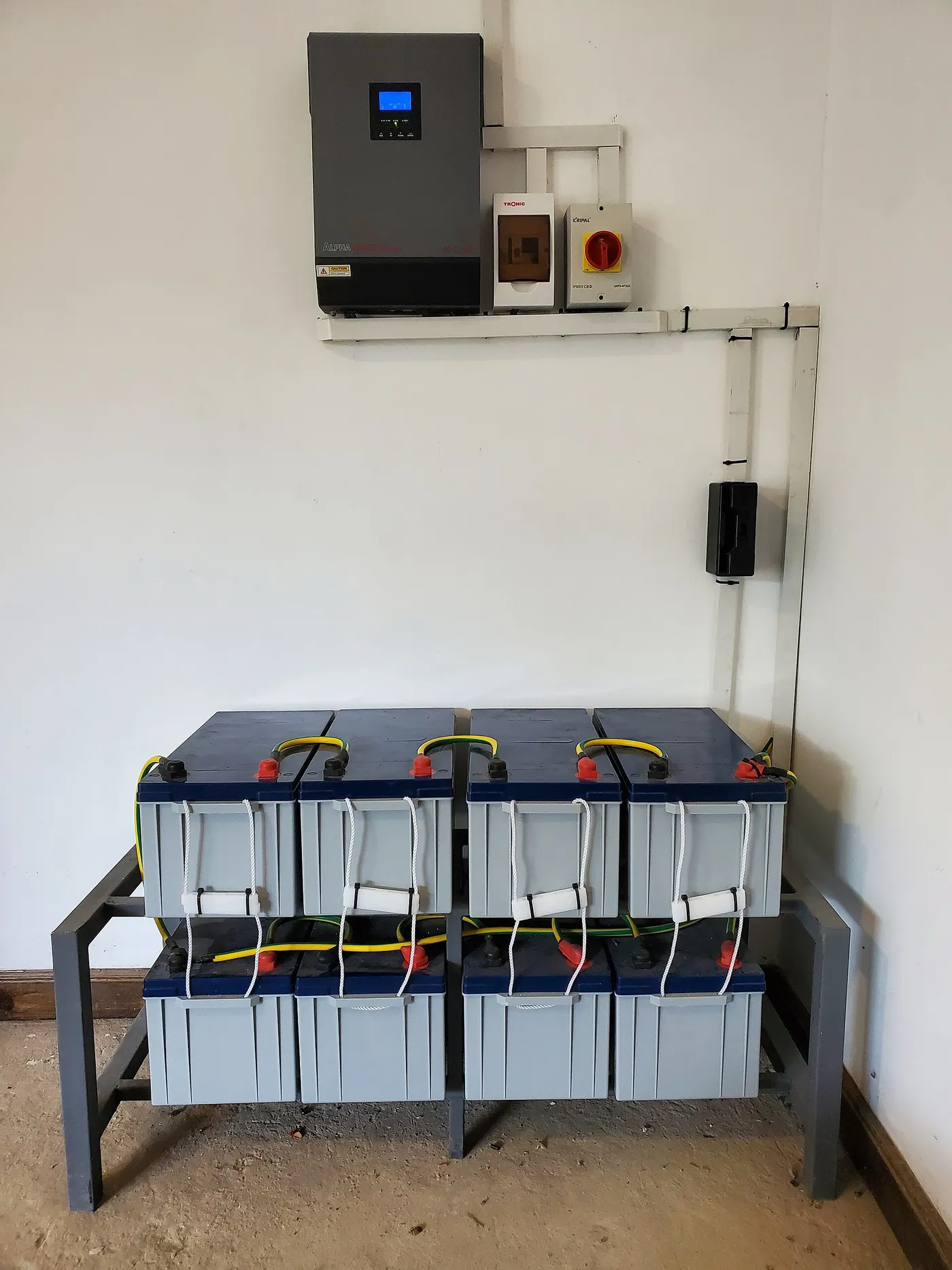
The formula that misses the dangerous limit
A common charge-controller sizing shortcut divides solar-array watts by battery voltage, adds a margin, and treats the answer as complete. That calculation can estimate charging current, but it does not check the input condition most likely to destroy a controller: excessive photovoltaic voltage on a cold, bright morning.
A controller sits between two electrical systems. On the input side, it receives the array's changing voltage and current. On the output side, it delivers regulated charging current to a battery bank with its own voltage, chemistry, temperature limits, and allowable charge rate. A correct design must fit both sides at the same time.
The safest method is a sequence of independent checks. Calculate maximum cold-weather open-circuit voltage. Check array short-circuit current. Estimate maximum battery-side charging current. Confirm permitted array power for the selected battery voltage. Then confirm the charging profile and environmental rating. Passing one check never excuses failure on another.
The four ratings that control the decision
| Rating to check | Where to find it | What must remain within it |
|---|---|---|
| Maximum PV input voltage | Controller datasheet | Array open-circuit voltage corrected for the coldest expected condition |
| Maximum PV short-circuit current | Controller datasheet | Combined array Isc for all parallel strings, including required design factors |
| Maximum charging output current | Controller datasheet | Expected current delivered to the battery side |
| Maximum permitted PV power | Controller table for each battery voltage | Total connected module watts under the manufacturer's oversizing rules |
Manufacturers do not always use identical terminology. A model name that contains two numbers may suggest input voltage and charging current, but the name is not a substitute for the datasheet. Read the manual for the exact hardware revision and operating voltage.
Some controllers permit more panel wattage than they can deliver continuously to the battery. This is called array oversizing. It can improve energy harvest during weak conditions, while the controller limits output during exceptional peaks. Oversizing is acceptable only within the manufacturer's explicit PV power, voltage, and current rules. It does not permit exceeding maximum input voltage.
Collect the source data before calculating
Start with the label or datasheet for every solar-panel model. Record rated power, open-circuit voltage or Voc, short-circuit current or Isc, maximum-power voltage or Vmp, maximum-power current or Imp, and the temperature coefficient of Voc. If modules differ, record each group separately. Do not assume two panels with the same watt rating have the same electrical characteristics.
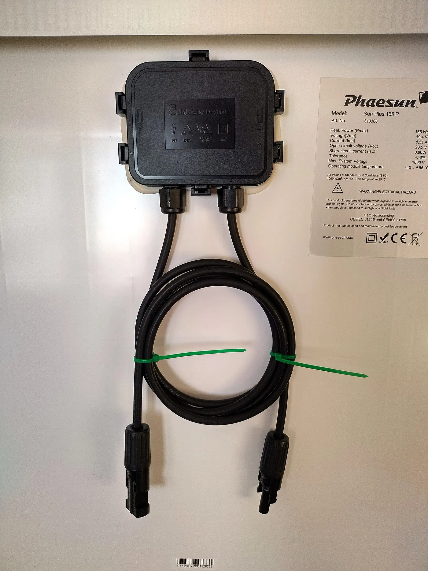
Next record the array configuration. Count modules in each series string and count the number of identical strings placed in parallel. Series connections add voltage while current stays approximately equal to one module. Parallel strings add current while voltage stays approximately equal to one string.
For the battery, record nominal system voltage, chemistry, capacity, recommended charging voltage, maximum allowable charge current, and temperature restrictions. A battery management system may disconnect a lithium bank outside its limits, but that protection is not a sizing strategy.
Finally, record the lowest credible temperature at the panel location, not only the normal winter daytime average. The design must account for unusual cold conditions in which an illuminated array can produce its highest open-circuit voltage. Module temperature may differ from air temperature, so follow the controller or module manufacturer's sizing method when one is provided.
Step one: calculate series-string Voc
Open-circuit voltage is measured when the module is illuminated but not supplying load current. For identical modules connected in series, add their Voc values. If one module has a Voc of 24 volts, three identical modules in series have a string Voc of 72 volts at the stated reference condition.
That result is not yet the design maximum because photovoltaic voltage rises as cell temperature falls. A string that appears safely below a controller limit at standard test conditions may cross the limit during cold weather. Exceeding maximum PV voltage can stop charging and can permanently damage the controller.
Use the module's published Voc temperature coefficient and the controller manufacturer's calculation method. A coefficient expressed as a percentage per degree requires a percentage correction from the reference temperature. A coefficient expressed in volts per degree requires a voltage correction. Do not interchange the formats.
If a manufacturer provides a string-sizing calculator, use the correct panel model, controller model, battery voltage, and site minimum temperature. Preserve the result with the system documentation. Online rules of thumb are not replacements for product-specific data.
Cold-weather voltage example
Consider four identical modules in series. Each lists a Voc of 22 volts at the reference condition, so the uncorrected string Voc is 88 volts. Assume the module documentation and minimum design temperature produce a cold correction multiplier of 1.12. The corrected string voltage becomes 98.56 volts.
That string does not belong on a controller with a 75-volt PV maximum. It may also be uncomfortably close to a 100-volt controller limit because measurement tolerance, colder-than-planned weather, and product instructions may require additional margin. The correct response is to change the series count or choose equipment with an appropriate input rating, not to hope the day remains warm.
The example multiplier is illustrative, not universal. A real project must derive its correction from the actual module coefficient, temperature data, and manufacturer instructions. This is the number competitors often omit when they present controller sizing as watts divided by volts.
Step two: check array short-circuit current
Series-connected identical panels do not add current in the way parallel strings do. If each string has a listed Isc of 6 amperes and three identical strings are connected in parallel, the unadjusted array Isc is 18 amperes. That value must be compared with the controller's maximum PV short-circuit current after applying any manufacturer and code-required design factors.
Do not confuse Isc with Imp. Imp is the current at the maximum-power operating point. Isc is the current measured under short-circuit test conditions and is used for protection and equipment-limit checks. Both appear on many module labels, and selecting the wrong one can understate the current requirement.
Parallel strings also affect overcurrent protection and conductor sizing. When one string faults, the others may feed current toward it. The panel's maximum series-fuse rating, number of strings, combiner arrangement, and applicable electrical rules determine whether individual string protection is required. Controller sizing and circuit protection are related, but they are not the same calculation.
Step three: estimate battery-side current
An MPPT controller can accept a higher PV voltage and convert available power to the lower battery charging voltage. As voltage steps down, available current can increase. This is why array Imp alone does not determine the required charging-current rating.
A planning estimate divides array power by the lowest relevant charging voltage and then accounts for conversion behavior and design margin. For example, 600 watts divided by 12 volts equals 50 amperes before losses or margins. The same nominal array connected to a 24-volt bank would imply about 25 amperes at that simple voltage assumption.
The controller manufacturer's array-power table is more authoritative than a rough calculation. Many models permit different maximum PV wattage on 12-, 24-, and 48-volt battery banks even though the controller's output-current rating remains the same. Check the row for the actual battery voltage.
Also compare the controller output with the battery's allowable charge current. A controller that can deliver 60 amperes is not automatically appropriate for a small battery that permits much less. Configure a lower charge-current limit if the controller supports it and the manufacturer approves that use, or select a controller matched to the bank.
MPPT and PWM do not size the same way
A maximum power point tracking controller can operate the array near its maximum-power voltage and convert power for battery charging. It commonly allows PV input voltage well above battery voltage, within its published limit. That flexibility makes series strings and longer cable runs practical in many installations.
A pulse-width modulation controller effectively pulls panel operating voltage toward battery charging voltage during parts of its operation. Panel and battery voltage matching is therefore more restrictive. Connecting a high-voltage array to a PWM controller can waste available voltage and may exceed the input rating.
The detailed operating comparison belongs in PWM vs MPPT charge controllers. For sizing, the key point is that the controller type changes how panel voltage becomes battery charging current. Never reuse an MPPT array design on a PWM controller without recalculating every limit.
Battery voltage changes the controller choice
At equal power, a higher-voltage battery system requires less charging current. A 1,200-watt charging target is approximately 100 amperes at 12 volts, 50 amperes at 24 volts, and 25 amperes at 48 volts before detailed voltage and efficiency adjustments. Lower current can reduce conductor size and voltage drop, but it does not make a voltage conversion automatically appropriate.
The controller must explicitly support the battery voltage, and all connected DC equipment must match the system. Some controllers detect battery voltage automatically, while others require configuration. Automatic detection can fail if the battery is disconnected, deeply discharged, or connected after the array contrary to the required sequence.
For a broader decision about system voltage, see 12V vs 24V vs 48V systems. This article assumes the battery-bank voltage is already selected and focuses on choosing a controller that fits it.
Battery chemistry and charge profile
A controller can fit every current and voltage rating yet remain unsuitable if it cannot provide the required charging profile. Flooded lead-acid, AGM, gel, and lithium iron phosphate batteries use different voltage targets and charging behavior. Manufacturer-defined absorption, float, equalization, low-temperature, and current limits matter.
Never apply an equalization profile to a battery chemistry that prohibits it. A fixed lead-acid profile is not automatically suitable for lithium. For LiFePO4, the battery-management system and controller must coordinate around charge voltage, current, and low-temperature charging restrictions. The chemistry background is covered in LiFePO4 vs lithium-ion batteries.
If a controller offers user-defined settings, that does not make arbitrary settings safe. Enter only the values supplied by the battery manufacturer. Confirm whether remote temperature sensing is required and where the sensor belongs.
Array oversizing and clipping
Solar modules rarely produce nameplate power for every hour. A manufacturer may therefore permit an array whose combined rated watts exceed the controller's maximum continuous charging output. During moderate conditions, the larger array can reach useful charging power earlier and maintain it later. During peak conditions, the controller limits or clips output.
Oversizing has hard boundaries. Cold-weather Voc must remain below maximum PV voltage. Array Isc must remain within the input-current specification. Connected watts must remain within the permitted oversizing ratio or maximum array-power table. Thermal and installation requirements still apply.
Do not infer permission from the fact that the controller can clip. Clipping output current does not guarantee protection against excessive input voltage. Voltage is the absolute check that must pass before array-power optimization is considered.
Sizing for an RV installation
An RV adds limited roof area, partial shade, vibration, cable-routing constraints, and changing climates. Record all roof-mounted panel specifications and calculate the coldest location the vehicle may visit, not only the climate where it is stored. A system designed for warm coastal use may exceed its controller voltage after the RV travels to a cold mountain region.
Roof vents, air conditioners, antennas, and luggage can shade individual panels. Series wiring may allow higher PV voltage and lower cable current, but one shaded module can restrict a series string. Parallel wiring can improve independence between strings but increases current and may require larger conductors and additional protection. The design belongs in the separate series vs parallel solar wiring article.
Buyers who prefer a coordinated hardware package can compare RV solar panel kits, but a kit label does not prove that its controller supports later expansion. Check how many additional modules can be added without exceeding voltage, current, or power limits.
Power-station and solar-generator inputs
A portable power station normally contains its own solar charge controller. The relevant limits are its stated solar input voltage range, maximum open-circuit voltage, input current, and accepted power. Users do not select an external controller unless the manufacturer specifically supports that configuration.
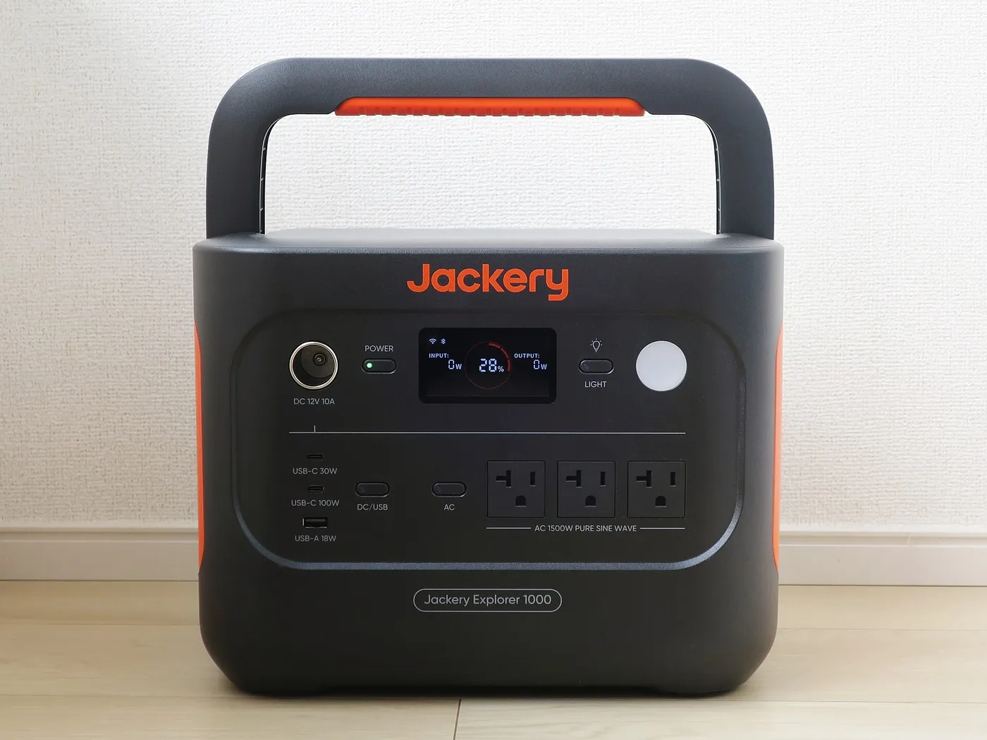
Before connecting third-party panels, compare the entire series or parallel array against those input limits and verify connector polarity. A plug that physically fits does not prove voltage compatibility. Avoid chains of undocumented adapters.
Selection guides for solar generators and RV solar generators can help identify products with suitable charging inputs. The sizing procedure remains the same: verify cold Voc, current, power, and supported connectors from primary documentation.
Wire size, fuses, and voltage drop
A correctly rated controller cannot compensate for undersized conductors or missing protection. Conductor ampacity must suit the circuit current, insulation temperature, bundling, installation environment, and applicable code. Voltage drop must remain acceptable over the actual round-trip cable length.
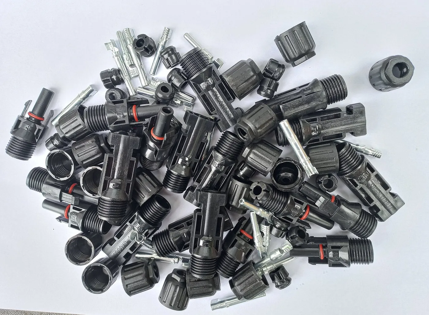
The PV side and battery side may require different conductor sizes. A high-voltage series array may carry relatively low current, while the controller-to-battery connection carries much higher current at lower voltage. Keep the controller close enough to the battery to limit voltage drop, while meeting ventilation and environmental instructions.
Place overcurrent protection and disconnects where required. The battery can deliver extreme fault current, so battery-side protection is critical. Follow the specified connection order. Many controllers require the battery to be connected before PV so the device can establish system voltage safely.
Environmental and thermal derating
Controller output may be reduced at high ambient temperature or poor ventilation. A unit rated for a particular charging current under favorable conditions may derate when installed in a hot, enclosed RV cabinet. Read the thermal derating curve and clearance requirements.
Ingress protection also matters. A controller designed for a dry interior location does not belong in an exterior compartment exposed to spray or condensation. Salt air, dust, insects, and vibration can shorten equipment life. Use the mounting orientation required for convection cooling and secure cables so movement does not load terminals.
Altitude can affect cooling and manufacturer ratings. If the system will operate in unusual heat or elevation, confirm the applicable limits rather than assuming the nameplate output is available everywhere.
Safety checklist before energizing
Solar modules produce voltage in light. Covering them may reduce output, but use the approved isolation procedure. Verify polarity with appropriate equipment before connection. Reverse polarity can damage a controller even when a connector appears correct.
Confirm that cold-corrected Voc is below the controller maximum, combined Isc is within the PV input rating, and battery-side current is within both controller and battery limits. Check fuse and disconnect ratings for direct current. Torque terminals to specification and recheck them after the recommended interval.
Do not connect or disconnect ordinary PV connectors under load. Direct-current arcs can persist. De-energize using listed equipment and follow the manufacturer sequence. Wear suitable protective equipment and use qualified help where the design or applicable electrical rules are uncertain.
Common sizing mistakes
- Using watts divided by nominal battery voltage as the only calculation. It omits cold-weather input voltage and array short-circuit current.
- Using Vmp instead of Voc for the voltage limit. Maximum PV input voltage is checked against corrected open-circuit voltage.
- Adding series-string current. Identical series modules add voltage; parallel strings add current.
- Ignoring travel climate. A mobile system must consider the coldest location it may encounter.
- Assuming clipping protects against overvoltage. It does not authorize an array whose Voc exceeds the input limit.
- Ignoring battery charge limits. The controller's capability can exceed what the battery safely accepts.
- Buying for current array size only. Planned expansion may require a higher input-voltage or output-current class.
A repeatable sizing workflow
- List panel Voc, Isc, Vmp, Imp, watts, and temperature coefficients.
- Draw the proposed series and parallel configuration.
- Calculate string Voc and correct it for minimum temperature.
- Calculate combined Isc for parallel strings and apply required factors.
- Estimate output current and check the controller's battery-voltage-specific PV power table.
- Confirm battery chemistry, charging voltage, current, and temperature requirements.
- Size conductors, protection, disconnects, and enclosures for both sides.
- Document the values and verify them against the current manuals before installation.
This workflow makes future changes easier. If a panel is added, a battery bank is changed, or the vehicle travels into colder weather, update the worksheet rather than guessing whether the original controller still fits.
Frequently asked questions
What size controller is needed for a 400-watt solar array?
There is no universal answer from wattage alone. Battery voltage affects output current, while panel configuration and temperature affect input voltage. Check corrected string Voc, combined Isc, controller output current, permitted PV watts at the battery voltage, and battery charge limits.
Can a solar charge controller be too large?
A higher current rating is not automatically harmful if the controller supports the battery voltage and its output can be configured within the battery's allowable charge current. It may be unnecessary, and its own consumption or minimum operating requirements may differ. Follow both manufacturers' instructions.
Can the array wattage exceed the controller output rating?
Only when the controller manufacturer explicitly permits array oversizing. Maximum PV voltage and short-circuit current must still remain within absolute limits, and connected watts must remain within the approved table or ratio.
Should controller current be based on Isc or Imp?
Use the parameter specified for each check. PV input short-circuit current limits and protection calculations use Isc. Maximum-power calculations use Vmp and Imp. Battery-side output sizing uses available power, charging voltage, controller rating, and battery limits.
Why does cold weather matter if solar panels produce less in winter?
Cold photovoltaic cells can produce higher voltage. Even when daily energy is modest, a bright cold morning can create the array's highest open-circuit voltage. That value must stay below the controller's maximum PV input voltage.
Can two controllers charge one battery bank?
It may be possible when both controllers and the battery manufacturer allow it, charging profiles are compatible, and total charging current remains within the battery limit. The controllers do not increase one another's PV input limits. Each array and controller must be sized independently.
Bottom line
A solar charge controller is correctly sized only when every independent limit passes. Start with cold-corrected array Voc, then check parallel-string Isc, battery-side charging current, permitted array power, battery chemistry, conductors, protection, and thermal conditions. The watts-divided-by-volts shortcut is useful as one estimate, not as a design. Use the exact panel, controller, and battery documentation, preserve reasonable margin, and recalculate whenever the array, battery voltage, climate, or system layout changes.