
The choice is about electrical limits
Series versus parallel is often presented as a contest with one winner. That framing creates bad designs. The two arrangements change different electrical quantities, and either can be appropriate when it matches the panels, controller, conductor run, climate, and shading pattern. A safe decision begins with equipment limits rather than a preference for one diagram.
In a series string, the positive lead of one panel connects to the negative lead of the next. Panel voltages add, while string current is limited near the current of one matched panel. In parallel, positive leads join together and negative leads join together. Voltage remains near the voltage of one panel, while branch currents add.
Those simple rules affect everything downstream. Higher voltage can reduce current for the same power and may reduce voltage drop on a long run. Higher current requires larger conductors, compatible branch connectors, and appropriate overcurrent protection. Series strings also create a higher cold weather open circuit voltage that must never exceed the charge controller input rating.
This article owns array configuration. It does not select a controller size, calculate a complete RV energy budget, or teach roof installation. Those choices use the array values produced here, but they require their own checks.
Series and parallel at a glance
| Characteristic | Series wiring | Parallel wiring |
|---|---|---|
| Array voltage | Panel voltages add | Stays near one matched panel voltage |
| Array current | Stays near one string current | Branch currents add |
| Long cable run | Lower current can reduce conductor loss | Higher current may require larger conductors |
| Main controller constraint | Cold corrected open circuit voltage | Input current and branch protection |
| Partial shade | A shaded panel can limit its string | Unshaded branches may continue contributing |
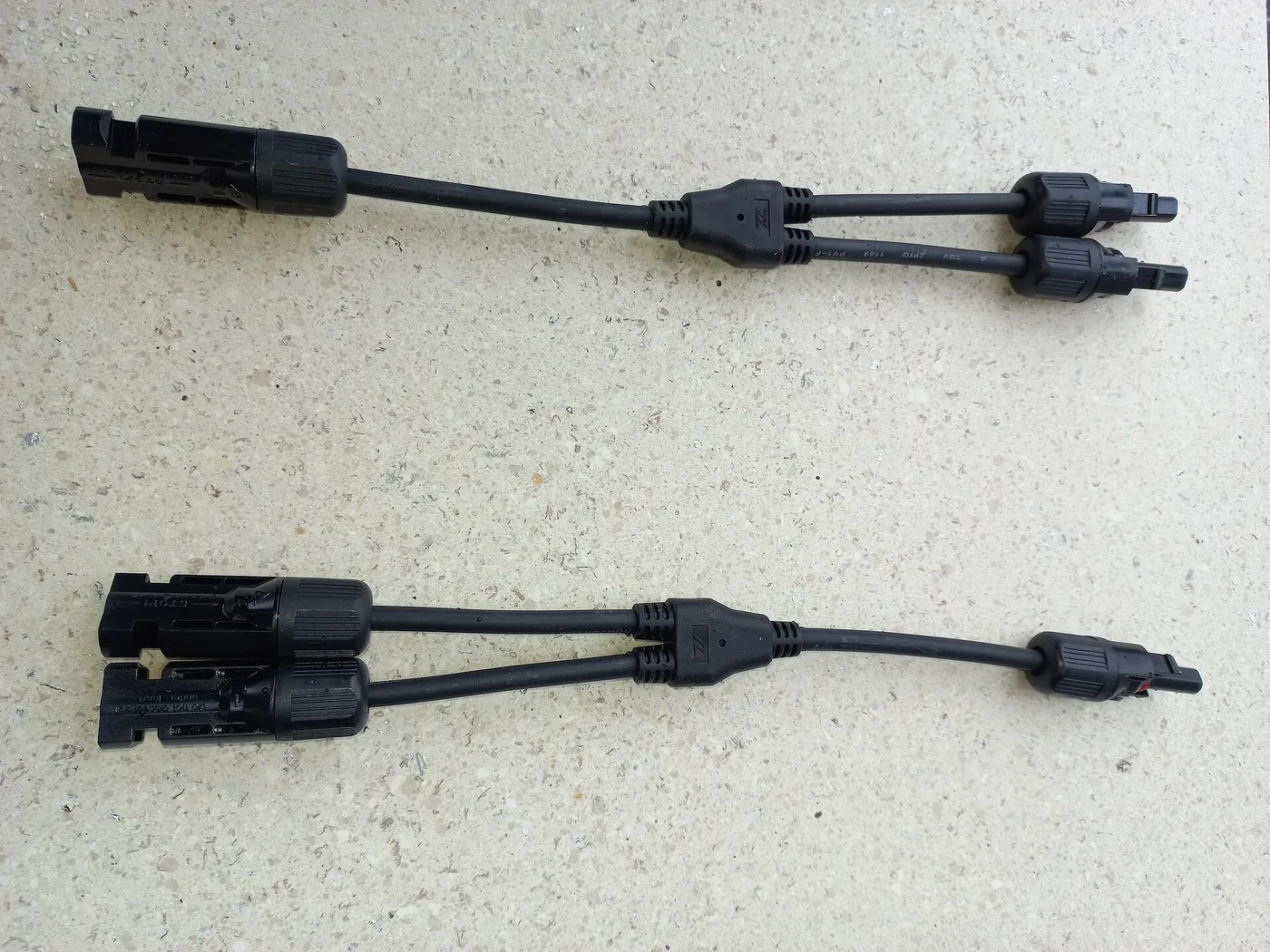
| Connections | Simple string connections | Branch connectors or a combiner may be required |
| Best fit | MPPT controller with adequate voltage headroom | Lower voltage arrays or installations with separate shade patterns |
The table describes the direction of change. It does not replace panel and controller specifications. Real panels have open circuit voltage, short circuit current, maximum power voltage, maximum power current, temperature coefficients, and maximum series fuse ratings. All of them can affect a compliant design.
How series wiring changes the array
Consider two matched modules. If each has a maximum power voltage of 20 volts and a maximum power current of 5 amps, a two panel series string operates near 40 volts and 5 amps at its maximum power point under the same conditions. Its nominal power is still the sum of the two panels. Series wiring changes the voltage and current relationship, not the total rated power available from the modules.
Open circuit voltage also adds. If each panel has a 24 volt open circuit rating, two in series create 48 volts at the standard reference condition. That is not yet the worst case. Solar module voltage rises as cell temperature falls. The design must apply the manufacturer's voltage temperature coefficient and the expected minimum site temperature, or use the controller maker's approved sizing method.
An array that appears comfortably below a controller limit on a warm afternoon can exceed it on a cold clear morning. Controller manufacturers warn that input voltage above the maximum can stop charging and may damage the controller. A casual safety margin is not a substitute for a temperature corrected calculation.
Series wiring is commonly paired with an MPPT controller. The controller can accept a PV voltage above battery charging voltage and convert that operating point into a suitable battery charging output within its ratings. A PWM controller does not use excess panel voltage in the same way, so a high voltage series layout can waste substantial potential or be incompatible. The distinction is covered in PWM vs MPPT charge controllers.
How parallel wiring changes the array
With the same two example panels wired in parallel, array maximum power voltage remains near 20 volts while maximum power current becomes about 10 amps. Open circuit voltage remains near one panel's value, and short circuit current becomes the sum of the branches.
Parallel wiring can be helpful when the controller has limited voltage headroom or when separate panels experience different shade patterns. An unshaded branch may continue contributing even if another branch loses current. That does not make parallel wiring immune to shade. A shaded module still loses production, bypass diodes still influence behavior, and the common operating voltage can create mismatch losses.
Added current changes conductor and connector requirements. Voltage drop is proportional to current for a given conductor resistance. Doubling current doubles the voltage drop across that resistance and increases resistive heating. A long parallel array run may therefore need a larger conductor than a series run carrying the same total power.
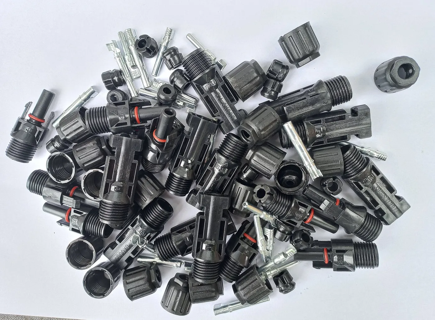
Every branch connector, combiner, fuse holder, disconnect, and controller terminal must be rated for the current and environment. Small molded connectors are not permission to combine unlimited branches. Check the connector rating, contact condition, cable size, and manufacturer limits. Poor crimps and mixed connector brands can create resistance and heat.
Series parallel combines both methods
Larger arrays often use matched panels in series strings, then connect identical strings in parallel. For example, four equal modules might form two strings of two panels. Voltage doubles within each string, and the two string currents add at the combiner.
A series parallel arrangement can keep voltage high enough for efficient conversion while keeping the string count within controller current limits. It can also fit a controller input window that neither all series nor all parallel would satisfy. The layout must remain balanced. Each parallel string should normally contain the same number and model of panels with similar orientation and exposure.
Unequal string voltage is especially problematic. Parallel branches share a common voltage, so strings with different numbers of panels should not simply be joined. A controller with multiple independent trackers may accept separate arrays, but each input must follow its manual. Multiple controller inputs are not automatically separate MPPT channels.
Draw the complete array before buying branch hardware. Label every module's voltage and current, show string polarity, and calculate the value at each combining point. This catches reversed connectors, unequal strings, and current ratings that a simplified shopping diagram may hide.
Shade changes the practical answer
In a series string, the same current flows through the connected path. If shade limits the current capability of one panel or cell group, it can restrict the string until bypass diodes conduct around the affected section. The exact loss depends on cell layout, diode grouping, shade direction, and how the MPPT controller finds an operating point.
In a parallel array, each branch contributes current at a common voltage. A shaded branch can fall while another branch continues producing. This often makes parallel attractive on RV roofs where vents, air conditioners, antennas, and roof racks cast different shadows across separate panels.
Parallel is not a cure for poor placement. If every module is shaded, no wiring method restores the missing sunlight. If panel orientations differ sharply, separate controllers or independent MPPT inputs may perform better than forcing unlike conditions onto one tracker. The placement analysis belongs in solar panel angle and shading losses.
Observe shade over time, not at one moment. A vent shadow moves across the roof as the sun changes position. Campsite trees and nearby vehicles add unpredictable patterns. Photograph or sketch the roof at several times when possible, and keep panels away from repeat shade sources before deciding how to wire them.
Cable loss favors voltage, but not at any cost
For the same power, transmitting at higher voltage requires lower current. Because conductor heating depends strongly on current, a higher voltage series arrangement can reduce loss or allow a smaller conductor for the same voltage drop target. This is useful when portable panels sit far from an RV parked in shade.
However, array voltage cannot be raised without limit. The controller has an absolute PV input voltage, connectors and disconnects have voltage ratings, and series open circuit voltage climbs in cold conditions. The best design uses enough voltage to operate effectively without approaching a limit that weather can cross.
Voltage drop should be calculated with the total circuit length, conductor material, cross section, expected current, and acceptable loss. The distance is the outgoing and return path, not merely the physical gap between array and controller. Flexible cords, connectors, fuses, and terminals also add resistance.
Do not solve voltage drop by accepting unsafe voltage or undersized protection. If a portable array needs a long lead, choose a compatible system voltage and cable intended for the current and outdoor use. Keep connectors dry, supported, and out of traffic paths.
Controller limits decide what is allowed
A controller may list maximum PV open circuit voltage, maximum PV short circuit current, maximum charging current, and recommended or maximum array power. These are different limits. Passing one does not prove that the others pass.
Series count controls the cold corrected open circuit voltage. Parallel string count controls summed short circuit current. The controller's battery side output rating limits how much charging current it can deliver. Some manufacturers permit array oversizing under defined conditions because the controller clips available power, but that permission does not allow input voltage or current limits to be exceeded.
Use the controller maker's sizing calculator when available and check the result against the current manual and panel datasheet. The article on how to size a solar charge controller walks through these independent limits. This wiring article supplies the array values that go into that process.
Battery voltage matters as well. A controller may accept different PV power at different battery bank voltages. A model name that contains a current and voltage number is not a full specification. Read the table for the actual system voltage and operating conditions.
Branch protection is not optional guesswork
Parallel strings can feed fault current into a damaged branch. Whether string fuses are required depends on the number of parallel sources, module maximum series fuse rating, conductor ampacity, controller instructions, and applicable electrical rules. Do not copy a fuse size from an unrelated array.
Protection must interrupt direct current at the system voltage. An AC breaker with a familiar current number is not automatically suitable for PV DC. Devices should be listed or specified for the intended DC voltage, current direction when relevant, enclosure, and environmental exposure.
Place protection and disconnects where the design and rules require them, not simply where they are easy to reach. Conductors should be protected from physical damage, ultraviolet exposure, heat, and sharp edges. Roof penetrations need strain relief and weather sealing.
A combiner box can organize parallel strings and house branch protection, but it does not correct an incompatible array. Verify enclosure rating, terminal torque, conductor range, and heat dissipation. Label circuits so future service does not require guessing.
Mixing panels requires more than matching watts
Two panels with the same rated watts may have different maximum power voltage and current. In series, current mismatch can cause the lower current module to restrict the string. In parallel, voltage mismatch can prevent both branches from operating at their individual best points.
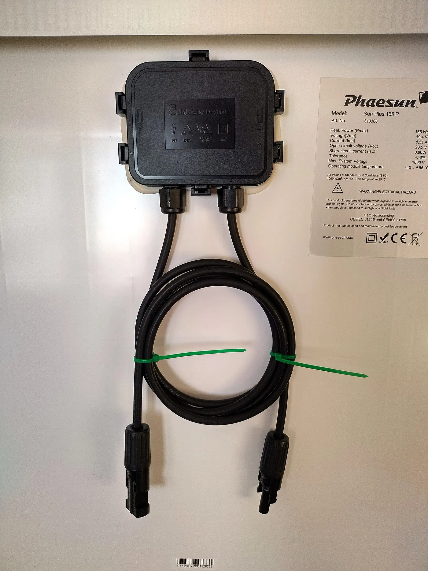
Matching model numbers are the simplest foundation. If panels must differ, compare maximum power voltage, maximum power current, open circuit voltage, short circuit current, temperature coefficients, orientation, and shading. A rough watt match is not enough.
Portable expansions create this issue frequently. An owner adds a folding panel to a roof array because the connector fits. The portable panel may have a different voltage class or built in controller. Never connect a controller output to another controller's PV input or parallel sources without confirming the intended architecture.
Buyers assembling a matched roof system can compare complete RV solar panel kits. Those kits can simplify component selection, but every included rating still needs verification against the vehicle, battery, and expected expansion.
RV roofs and portable arrays favor different layouts
An RV roof has short cable runs but frequent partial shade. Parallel or short series strings may preserve production when separate roof areas shade differently. Higher current and roof combiner requirements must still be addressed. A layout drawing should show vents, service access, cable entry, and the direction of panel cell strings.

A portable array often has a longer cable run from the sunny deployment area to a vehicle parked in shade. Higher array voltage can reduce loss, making a series arrangement attractive when the controller has sufficient cold voltage headroom. Portable connectors and cords must be protected from vehicles, feet, water, and repeated bending.
Folding products may wire their internal sections in a fixed arrangement. Do not assume that two visible panel leaves can be rewired individually. Use the product's published output values. The best foldable solar panels guide can help compare deployment products after the electrical input requirement is known.
Small modules used for light charging may operate at a lower voltage and current, but the same principles apply. The solar panels under 50 roundup covers that product class without changing the need to check polarity and controller compatibility.
A step by step configuration method
First, collect the current datasheet for every panel and the manual for the exact controller. Record module maximum power voltage and current, open circuit voltage, short circuit current, temperature coefficients, and maximum series fuse rating. Record every controller input and output limit.
Second, draw candidate layouts. Calculate series voltage using the number of panels per string. Correct open circuit voltage for the lowest expected temperature. Reject any layout that can exceed the controller maximum.
Third, calculate parallel current. Sum string short circuit currents and compare them with the controller input current rating. Calculate operating current for conductor voltage drop and ampacity. Determine branch protection from equipment instructions and applicable rules.
Fourth, evaluate exposure. Map shade and orientation for each panel. Keep similarly exposed modules together. If roof and portable panels face different conditions, consider independent controller channels rather than forcing both onto one tracker.
Fifth, confirm every component between panel and controller. Check cables, connectors, branch devices, combiner, disconnect, glands, terminals, and grounding or bonding provisions. Finally, document polarity and expected readings for commissioning.
Commissioning and troubleshooting
Before energizing, inspect polarity, connector engagement, cable support, protection, and controller configuration. Follow the connection sequence in the controller manual. Some controllers require the battery to be connected before PV so they can identify system voltage correctly.
Measure only with instruments, probes, and protective procedures rated for the possible DC voltage. Open circuit measurements can confirm string polarity and approximate voltage, but a normal open circuit value does not prove that every connection can carry current safely.
If a series string produces low power, compare current and voltage with expected conditions and check for shade, a bypassed section, loose connectors, or mismatched panels. If a parallel array is low, inspect individual branch contribution using an approved isolation procedure. Do not unplug live PV connectors to see what changes.
Record baseline controller readings in clear weather, including PV voltage, PV current, charging output, and battery state. Later comparisons are more useful when time, weather, temperature, and load conditions are similar.
Safety for series and parallel arrays
Illuminated panels are live sources. A battery disconnect does not remove PV voltage from the array side of a controller. Series strings can create hazardous voltage, while parallel arrays can create high fault current. Treat both configurations as energized until isolated and verified using the approved procedure.
Never mate or separate connectors under load unless the connector and procedure explicitly permit it. DC arcs can persist and damage contacts. Use compatible connectors from an approved system, correct crimp tooling, and weather seals. Mixing lookalike connectors can produce poor contact pressure and overheating.
Covering panels can reduce production but may not establish a verified safe state. Follow equipment manuals, use rated disconnects, and obtain qualified help where required. Roof work adds fall hazards, and portable arrays add trip and vehicle hazards.
Stop operation if a connector is discolored, hot, melted, cracked, wet inside, or producing an odor. Isolate the system safely and replace damaged components with compatible rated parts. Do not tape over a failing connector and return it to service.
Frequently asked questions
Is series or parallel better for solar panels?
Neither is universally better. Series raises voltage and can reduce cable loss, while parallel raises current and can preserve output from separately shaded branches. The correct layout must satisfy controller voltage, current, power, conductor, protection, and exposure requirements.
Does series wiring increase solar panel watts?
No. It adds panel voltage while current remains near the string current. The rated powers of the panels still add regardless of a compatible series or parallel arrangement. Wiring changes how that power is delivered.
Can panels with different watt ratings be connected together?
They can sometimes be combined, but wattage alone is insufficient. Current mismatch affects series strings and voltage mismatch affects parallel branches. Compare all electrical specifications and controller requirements before mixing modules.
Why does cold weather matter for series strings?
Solar panel open circuit voltage rises as cell temperature falls. Because series voltages add, a string that is safe at the standard test temperature can exceed a controller input limit on a cold clear morning.
Does parallel wiring work better in shade?
It can allow unshaded branches to continue contributing when another branch is shaded. Results still depend on panel design, common operating voltage, bypass diodes, and shade pattern. Good placement remains more effective than relying on wiring to fix shade.
Can I use branch connectors without fuses?
Do not decide from connector appearance alone. Branch protection depends on parallel source count, module fuse rating, conductor ampacity, equipment instructions, and applicable rules. Use a design reviewed for the specific array.
Bottom line
Series wiring adds voltage and keeps current near one string value. Parallel wiring keeps voltage near one panel value and adds branch current. Use series when higher voltage improves transmission and the controller has safe cold weather headroom. Use parallel when lower voltage or independent shade behavior makes it the better fit, while accounting for higher current and branch protection. Calculate every hard limit separately, match panels where possible, document the layout, and never treat a fitting connector as proof that the system is electrically safe.