The roof hole is not the first step
The most expensive RV solar installation mistakes often happen before a wire is connected. A panel is positioned where an air conditioner shades it, a fastener misses structural support, a cable entry blocks future roof service, or a sealant is chosen without checking roof compatibility. Drilling first and planning later turns a reversible layout problem into a leak risk.
A sound installation begins with documentation. Obtain the RV roof construction information, panel manual, mounting hardware instructions, charge controller manual, battery requirements, and applicable electrical rules. Confirm whether the RV manufacturer permits the proposed attachment method and whether the roof can support installers, panels, brackets, and travel loads.
This article explains the physical sequence and the checks that connect one stage to the next. It does not calculate how many panels the RV needs. Complete system sizing first, then use the chosen modules, controller, battery, and conductor requirements to create an installation plan.
Separate design decisions from installation work
Installation cannot correct an incompatible design. Before mounting hardware reaches the roof, confirm that the array open circuit voltage at the coldest expected temperature remains below the controller maximum. Confirm array current, controller output current, battery charging profile, conductor ratings, disconnects, and overcurrent protection.
Verify panel dimensions and weight against the scaled roof layout. Check cable lengths without relying on the straight line distance. Conductors must follow protected routes, include service loops where instructed, and reach terminals without tension. Connector pairs must be compatible by manufacturer and type, not merely able to click together.
Decide whether panels will be wired in series, parallel, or a series parallel arrangement. That configuration changes voltage, current, connector count, protection requirements, and shade behavior. It also changes the number of roof branches that must enter a combiner or cable entry. Record the approved wiring diagram and keep it with the RV documents.
For product selection after the design requirements are known, the best RV solar panels guide compares roof oriented options. A packaged set from the best RV solar panel kits guide can simplify parts selection, but every included component still needs to be verified against the RV and electrical design.
Survey the RV roof and interior route
Inspect the roof in dry daylight. Identify membrane type, seams, previous repairs, soft areas, cracks, loose trim, and existing penetrations. Any roof defect should be repaired through an appropriate method before solar hardware is added. Mounting over a weak or wet roof conceals the problem and makes later repair harder.
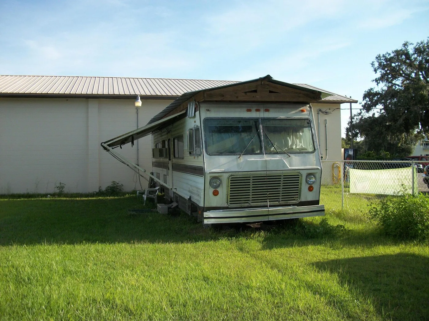
Locate structural members using manufacturer documentation or a suitable approved method. Do not assume that visible interior cabinets identify roof framing. Note the position of concealed electrical wiring, ducts, plumbing, and air conditioner components before selecting any fastener length.
Inside the RV, trace a route from the roof entry to the charge controller and from the controller to the battery. The route should protect conductors from abrasion, stored cargo, heat, sharp metal, hinges, slides, and water. Avoid flues and other hot cavities. Maintain separation and support required by the equipment instructions and applicable code.
Place the controller where its manual permits. It may need ventilation and specific clearance. A long array side cable run may be acceptable at higher photovoltaic voltage, while the controller to battery run often carries greater current and benefits from being short. This does not authorize arbitrary placement, but it explains why the entire route must be considered rather than choosing a controller location for visual convenience.
Plan around shade and service access
Roof equipment creates shadows that move during the day. Air conditioners, vents, antennas, satellite equipment, racks, and raised edges can shade cells when the sun is low. Observe the roof or model sun direction for the travel season. A panel that appears clear at noon may receive a long obstruction shadow during valuable morning or afternoon production.
Leave room to remove vent covers, service an air conditioner, inspect seals, and reach junction boxes. Do not create a layout that requires stepping on a panel to maintain another component. Preserve roof drainage paths and do not place cables where water can pool around a gland or bracket.
Consider future additions. An empty, accessible route or a slightly larger approved cable entry can be useful, but unused openings must remain properly sealed. Do not install conductors or connectors beyond their ratings merely because a future expansion is possible.
Smaller modules can fit around obstacles. Candidates in the best 100 watt RV solar panels guide may suit fragmented roof areas, but more modules mean more mounts and electrical connections. The layout should balance fit with serviceability and connection count.
Choose a mounting method the roof allows
| Mounting approach | Potential advantage | Main installation check |
|---|---|---|
| Fastened rigid brackets | Direct mechanical attachment | Approved structure, fastener type, length, sealing, and roof warranty |
| Bonded brackets | May avoid some roof penetrations | Roof material, adhesive system, surface preparation, cure, and travel loads |
| Tilt hardware | Allows seasonal angle adjustment | Travel locks, wind exposure, access, and safe deployment |
| Roof rack attachment | Uses an existing support system | Rack capacity, clamp compatibility, vibration, and panel clearance |
| Portable panel instead | No permanent module mount | Storage, theft control, cable routing, weather, and daily deployment |
No mounting method is universally safe for every RV. A bonded bracket depends on a verified adhesive system and compatible substrate. A mechanical fastener depends on suitable structure and careful waterproofing. Combining random adhesive, sealant, and tape products does not create a tested assembly.
Use the bracket maker's required number of supports and attachment points. Do not remove mounts to reduce roof penetrations or improvise a bracket that concentrates load on the panel frame. Maintain any ventilation gap specified by the module or mounting manufacturer.
Prepare surfaces and hardware correctly
Surface preparation determines whether a bonded or sealed joint performs. Clean only with products approved for the roof membrane, bracket, adhesive, and sealant. Some solvents damage roofing or leave residue. Follow the required cleaning, abrasion, primer, application temperature, humidity, and cure time.
Dry fit every bracket before applying adhesive or sealant. Mark orientation and confirm that panel frame holes align without forcing the frame. Stainless hardware may require measures against galling or dissimilar metal corrosion as directed by the manufacturer. Use specified washers, locking components, and torque.
For penetrations, verify fastener diameter and length. A longer screw is not automatically stronger if it reaches wiring or passes beyond useful structure. Apply the sealing system in the exact order specified. Sealant over a loose fastener does not restore the mechanical joint.
Respect cure time before installing the panel or driving the RV. Air temperature, surface temperature, and humidity can change cure behavior. A mount that feels firm at the surface may not have reached the required strength underneath.
Mount the panels without stressing the frame
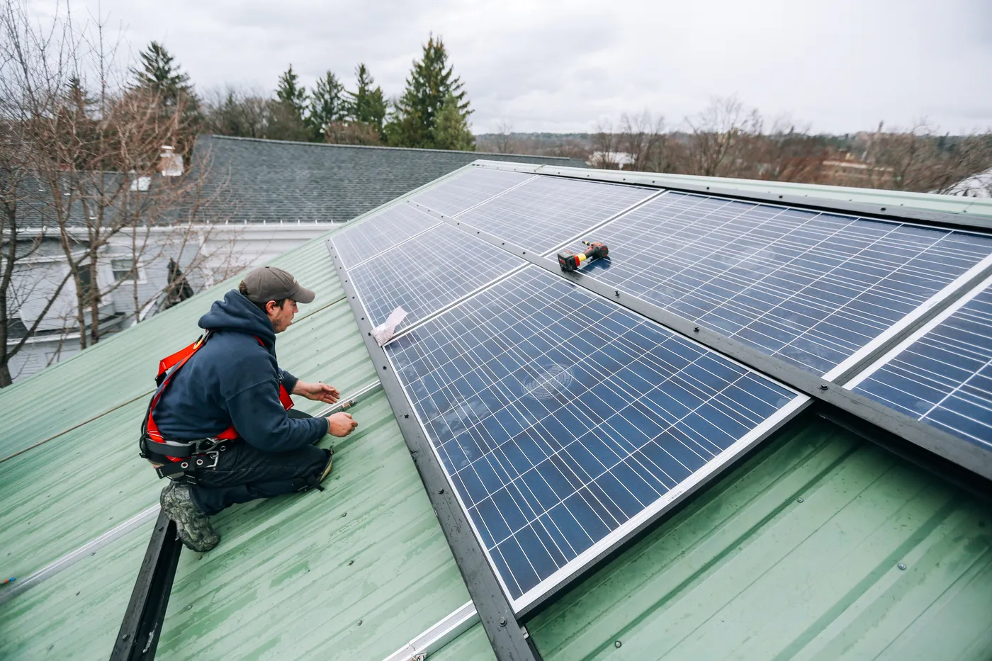
Move panels onto the roof using enough people and an appropriate lifting method. A module is awkward in wind and can act like a sail. Protect the roof from tools and panel corners, and maintain fall protection suitable for the work.
Attach brackets only at frame locations permitted by the module instructions. Do not drill new holes through the panel frame unless the manufacturer expressly allows it. Improvised holes can weaken the frame, create metal chips, damage wiring, and affect warranty coverage.
Set the panel onto all supports without twisting it to meet misaligned brackets. Tighten hardware in a controlled pattern and to specified torque. Over tightening can deform the frame or crush components, while under tightening can allow vibration and movement.
Confirm that tilting hardware is locked in the travel position. A raised panel can experience severe wind load while driving. Use only the intended travel restraints and include their inspection in the departure checklist.
Route roof cables for movement and weather
Photovoltaic cables on an RV roof face ultraviolet light, water, heat, vibration, and airflow. Use conductors and connectors rated for the environment and electrical conditions. Secure cables at intervals and with methods permitted by the cable and roof manufacturers.
Keep conductors off sharp edges and away from moving vent lids, antenna arms, slide mechanisms, and hot equipment. Prevent cable loops from whipping in airflow. At the same time, provide a modest service loop where required so connectors are not held under tension.
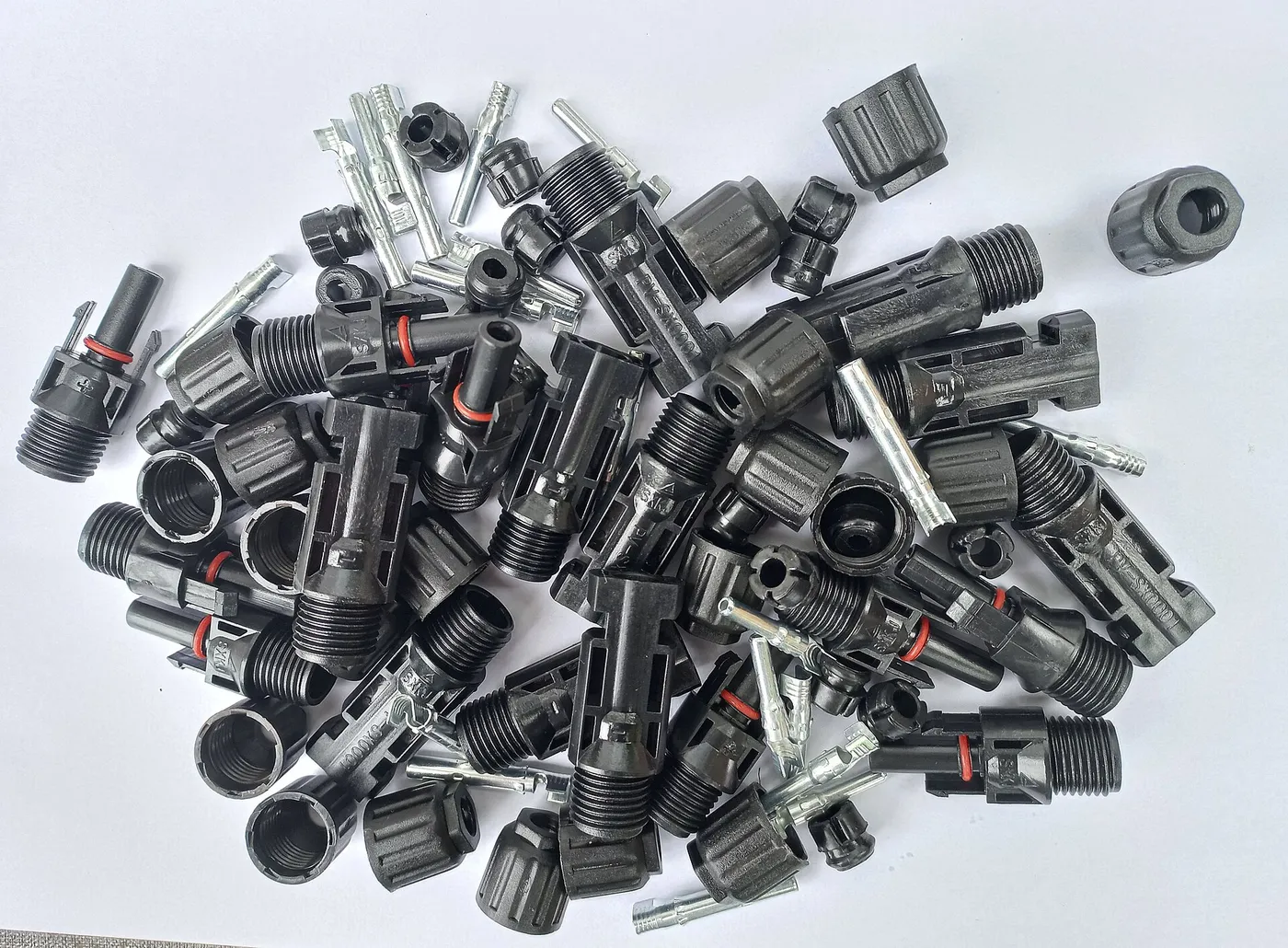
Support both sides of a connector. A connector should not hang where its weight pulls on the cable or where water collects around it. Keep mating surfaces clean and dry during assembly. Follow the connector maker's strip length, crimp tool, die, contact insertion, and pull test instructions.
Do not splice roof cable with household wire nuts, unlisted taps, or a connector assembled from mixed brands. Physically compatible looking photovoltaic connectors can have different tolerances and materials. A poor contact can heat under sustained current.
Build a weatherproof roof entry
The roof entry must protect the cable, control water, and remain serviceable. Select an entry gland or box rated for the conductor diameter, cable count, roof environment, and installation method. Confirm that the gland compression range actually matches the cable.
Position the entry where water drains naturally and where it can be inspected. Avoid a low spot or the direct discharge path from an air conditioner. Inside, protect the hole edge with the specified bushing or fitting so vibration cannot abrade insulation.
Create a drip path that does not guide water toward the opening. Follow the entry maker's orientation instructions. Apply compatible sealant to a properly prepared surface and maintain the required flange coverage without blocking intended drainage or gland operation.
After cure, inspect for gaps, movement, and cable tension. Water testing should follow the RV and sealing system guidance. High pressure spray can force water into joints in a way normal rain does not and can damage roof components.
Understand series and parallel before connecting
Series connections add panel voltage while current remains limited by the string. Parallel connections add current while voltage remains similar. This changes conductor current, controller input, connectors, and overcurrent protection. Use the approved array diagram rather than assembling connections by convenience.
Series wiring can reduce current for a given array power and may improve operation when the panel voltage must remain above the battery charging voltage. However, open circuit voltage rises in cold weather, and shade or mismatch can limit a series string. Parallel wiring keeps voltage lower and can allow unshaded branches to contribute independently, but it increases current and may require branch protection.
Do not calculate a series string from operating voltage alone. Add module open circuit voltage and apply the required temperature correction for the expected coldest condition. The result must remain below the controller's absolute maximum photovoltaic input voltage.
The article on series versus parallel solar wiring owns the full configuration comparison. During installation, the essential rule is to follow the completed design and label each string so polarity and connection order remain clear.
Size and protect the conductors
Conductor size depends on maximum current, insulation temperature rating, installation environment, bundling, route, voltage drop target, terminal limits, and applicable electrical rules. A cable that appears thick enough may be unsuitable for roof exposure or the expected temperature.
Protection must be selected for the conductors and circuit, not merely the panel wattage. Parallel strings can feed current into a faulted branch. Battery conductors deserve particular attention because a battery can supply very high fault current. Place battery side protection as required near the source and protect every conductor segment according to the system design.
Use disconnects rated for direct current at the maximum circuit voltage and current. An AC switch or breaker may not interrupt a DC arc safely. Labels should identify the solar array, controller, battery, disconnect positions, and any source that can energize the circuit.
Route positive and negative conductors together where appropriate to reduce loop area, and support them against vibration. Use grommets or listed fittings at every metal passage. Do not depend on insulation alone where a cable crosses a raw edge.
Place and connect the charge controller
Mount the controller in a dry location within its permitted temperature range and clearances. Cooling vents and heat sinks need airflow. Do not place ignition protected and non ignition protected equipment in battery or fuel compartments contrary to their listings and instructions.
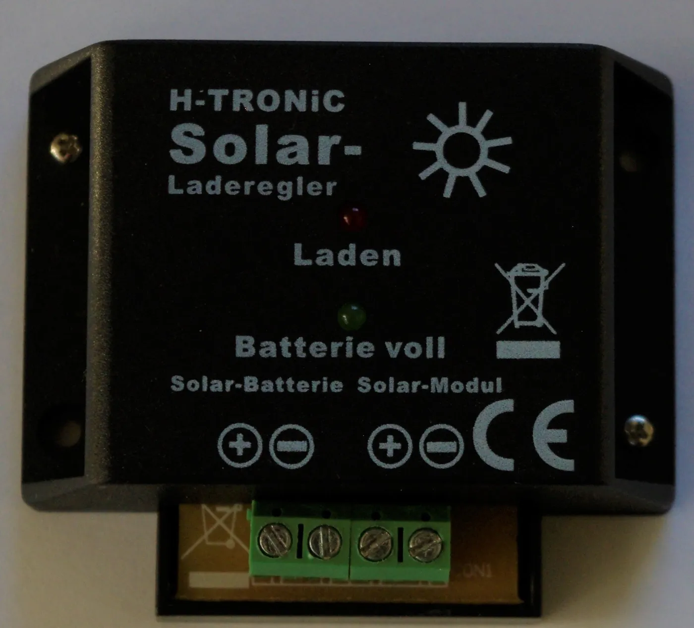
The controller to battery path commonly carries more current than the roof array path. Keep it appropriately short, use the required conductor size, and install protection and disconnects from the approved diagram. Voltage drop in this segment can make the controller read a higher voltage than the battery actually receives and can impair charging.
Many controllers require the battery to be connected before the photovoltaic array so the controller can identify system voltage and initialize correctly. Others have a defined commissioning sequence. Follow the exact manual. Do not assume one sequence applies to every product.
Program battery chemistry, charge voltages, current limit, temperature behavior, and communication settings only from the battery and controller documentation. Lithium batteries may prohibit charging below a specified temperature unless heating or battery management controls provide protection.
Connect the battery side safely
De energize all sources using the planned isolation procedure. Remove jewelry, control tools, and protect exposed terminals. Verify polarity with an appropriate meter before making the final connection. A reverse polarity event can damage equipment and create an arc.
Use terminals, lugs, and crimping methods approved for the conductor. Support heavy cable so it does not load controller or battery terminals. Apply terminal torque from the equipment specification and record it for inspection. Do not place washers where they interrupt the intended electrical contact surface.
Battery bank wiring should distribute charge and load current as the battery manufacturer directs. Parallel batteries require careful symmetry or busbar arrangement. Every battery must be secured against travel movement and protected from cargo or dropped tools.
The broader voltage implications are covered in 12V vs 24V vs 48V systems. Installation should never mix nominal voltage equipment or assume a device marked 12V can tolerate the charging voltage of every 12V battery chemistry.
Commission the system in stages
Before energizing, perform a visual and mechanical inspection. Confirm bracket attachment, sealant cure, cable support, connector engagement, polarity labels, conductor protection, controller clearance, battery mounting, fuse ratings, and disconnect positions. Compare every connection with the approved diagram.
Measure string open circuit voltage and polarity with an appropriate meter and safe procedure before connecting the array to the controller. The measured value should be plausible for the number of modules, temperature, and light conditions. An unexpected value requires investigation, not an attempt to see whether the controller accepts it.
Energize in the sequence specified by the equipment manufacturers. Confirm controller startup, battery detection, programmed chemistry, photovoltaic voltage, charging current, alarms, and temperature. Begin with major loads off. Then add loads deliberately while watching connections and system status.
After the first charging period, inspect for abnormal heat, odor, noise, discoloration, loose cable support, or controller warnings. Thermal inspection should use a safe method and account for sun heated surfaces. Shut the system down if a connector or conductor is unexpectedly hot.
Document and maintain the installation
Create a final diagram showing panel models, string configuration, conductor sizes, connector types, fuse and breaker ratings, disconnects, controller settings, battery details, and cable route. Photograph concealed routes before closing panels or cabinets. Keep torque values, manuals, and sealant product information with the record.
Inspect roof mounts and cable support on the schedule required by the manufacturers and after severe weather, branch impact, roof service, or unusual vibration. Look for cracked sealant, lifted edges, loose hardware, cable abrasion, connector movement, corrosion, water staining, or debris around panels.
Roof sealants age and roof materials move. Maintenance should use compatible products and preserve the designed joint rather than repeatedly covering it with unrelated sealant. If water intrusion is found, locate the actual path and repair the assembly rather than coating a broad area without diagnosis.
Check system data for changes in production that cannot be explained by weather or season. A persistent reduction may indicate shade, dirt, a loose connection, controller setting, battery limitation, or module problem. Electrical faults should be evaluated safely rather than diagnosed by disconnecting live connectors.
When portable solar is the better installation
A roof installation is not mandatory. A portable panel can be placed away from tree shade and aimed toward the sun while the RV remains in a comfortable campsite. It also avoids permanent roof mounting, although a safe charging connection is still required.
Portable systems introduce daily handling, storage, wind stability, cable trip hazards, theft risk, and weather exposure. Long cable runs can add voltage drop. Connectors must remain protected from dirt and water, and a panel should not be left where a vehicle can drive over its cable.
An integrated portable battery system may suit travelers who do not want permanent wiring. The best RV solar generators guide compares that approach. It does not remove the need to match panel input voltage, current, polarity, and connector requirements.
Frequently asked questions
Can RV solar panels be screwed directly into the roof?
Only when the RV, mounting system, and panel instructions approve the attachment and the fasteners enter suitable structure. The penetration also needs the specified waterproofing system. Do not select a fastener location from the roof surface alone.
Can adhesive mounts replace screws?
Sometimes, but only as a verified system. Roof material, bracket area, adhesive, surface preparation, environmental limits, cure, panel size, and travel loads all matter. Generic adhesive advice is not a substitute for manufacturer approval.
Should the battery or solar panels be connected first?
Follow the controller manual. Many controllers require battery connection before photovoltaic input, but the required sequence is product specific. Commissioning and shutdown may use different orders.
Can solar connectors be disconnected in sunlight?
Do not disconnect them under load unless the equipment and procedure specifically permit it. DC arcing can persist. Isolate sources with correctly rated disconnects and follow the documented shutdown sequence.
Where should the charge controller be installed?
Use a dry, ventilated location within the controller's allowed temperature and clearance limits. The controller to battery cable should generally be kept suitably short because it carries charging current, but all location requirements must be satisfied.
How often should roof mounts be inspected?
Use the RV, bracket, adhesive, sealant, and panel maintenance schedules. Also inspect after severe weather, an impact, roof service, or unusual travel conditions. Any movement, cracking, abrasion, or water staining requires investigation.
Bottom line
A reliable RV solar installation is built from a verified design, a roof layout that respects structure and shade, mounting hardware installed as a complete approved system, protected cable routes, a weatherproof entry, and correctly rated DC wiring and protection. Plan every penetration and connection before work begins. Follow product specific connection order, verify polarity and voltage before energizing, commission the system in stages, and document the finished installation for future maintenance. When the roof or electrical work is uncertain, qualified installation is safer than improvisation.